
Pose measurement device and compliance control method for spacecraft docking and capture process

A capture process, pose measurement technology, applied in space vehicle docking devices, photo interpretation, etc., can solve the problems of docking mission failure, large contact force fluctuations, inability to accurately compensate friction, damping parameters, etc., to reduce capture The effect of failure probability

Active Publication Date: 2020-09-01
HARBIN INST OF TECH
View PDF5 Cites 0 Cited by
  • Summary
  • Abstract
  • Description
  • Claims
  • Application Information

AI Technical Summary

Problems solved by technology

[0005] The present invention adopts Stewart structure in order to solve the docking capture of existing spacecraft, and installs a six-dimensional force sensor on each drive rod or docking ring. Through the detection of contact force, it uses the principle of impedance control to perform compliance control. There is a docking mechanism in this way. The driving force cannot accurately compensate the change of friction and damping parameters, resulting in large fluctuations in contact force, resulting in the failure of the docking task. A pose measurement device and a compliant control method for the docking and capturing process of a spacecraft are provided.

Method used


Image

  • Pose measurement device and compliance control method for spacecraft docking and capture process
  • Pose measurement device and compliance control method for spacecraft docking and capture process
  • Pose measurement device and compliance control method for spacecraft docking and capture process

Examples


specific Embodiment approach 1

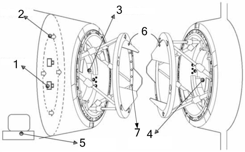
[0034] Specific implementation mode one: combine figure 1 Describe this embodiment, this embodiment includes active docking mechanism 3, passive docking mechanism 4, binocular camera 1, data processing and motion control computer 5 and active lighting system,

[0035] The active docking mechanism 3 is a heterogeneous isomorphic peripheral docking mechanism with the guide plate 6 turned inside out, which is used for data connection such as compliant capture, rigid connection, etc. of the tracking spacecraft and the target spacecraft during the docking process; for example: developed by the Soviet Union / Russia The APAS-89 docking mechanism is a weak impact docking mechanism designed by NASA. These mechanisms all have the structural characteristics of the heterogeneous isomorphic peripheral docking mechanism with the guide plate turned inside out, that is, the docking mechanism adopts the Stewart structure and uses the guide plate for guidance. The passive docking mechanism 4 is...

specific Embodiment approach 2

[0041] Specific implementation mode two: combination figure 1 Describe this embodiment. In this embodiment, the two cameras of the binocular camera 1 are symmetrically installed on both sides of the center projection point of the docking ring at the initial position of the active docking mechanism 3. At the same time, the pixels of the cameras meet the measurement accuracy requirements. In addition, during the docking process, the active docking Mechanism 3 and passive docking mechanism 4 are always within the observation field of view of the two cameras, clear and unobstructed. It should be noted that if in a spacecraft such as a manned spacecraft or a cargo spacecraft, the installation position of the binocular camera 1 must not affect the passage of astronauts and cargo, and can be unloaded together with the hatch or transferred to a specific position, for example, in In a manned spacecraft, the binocular camera 1 can generally be installed at the hatch at the bottom of the...

specific Embodiment approach 3

[0042] Specific implementation mode three: combination figure 1 , figure 2 and image 3 Describe this implementation mode, this implementation mode includes the following steps;

[0043] Step 1: Use the binocular camera 1 to collect and capture images of the guide plate 6 of the active docking mechanism 3 and the guide plate 6 of the passive docking mechanism 4 during the capture process;

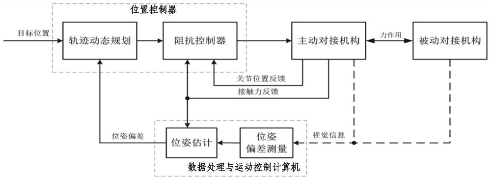
[0044] Step 2: Data processing and motion control The computer 5 processes the image of the guide plate 6 collected by the binocular camera 1: first preprocesses the image of the guide plate 6 collected, and recognizes the preprocessed image according to the characteristics of the guide plate 6 Out of the guide plate 6; then use the principle of binocular stereo vision to calculate the pose of the identified guide plate 6 based on the camera coordinate system; then obtain the pose deviation between the active docking mechanism 3 and the passive docking mechanism 4 through vector calculat...


PUM


Abstract

The invention provides a position and posture measurement device of a spacecraft docking capture process and a compliant control method. The device comprises: a binocular camera, an active illuminating system and a data processing and motion control computer, wherein the binocular camera is mounted on the bottom surface in a docking mechanism; a main light source and an auxiliary light source of the active illuminating system are mounted on an inner cylindrical surface of a docking ring and the bottom surface in the docking mechanism respectively. The method comprises the following steps: combining a binocular vision measurement device with an impedance control method to realize weak collision even no collision in the spacecraft docking capture process; acquiring and identifying guide plate images of active and passive docking mechanisms in the capture process by utilizing the device and calculating a position and a posture, based on a camera coordinate system, of a guide plate; obtaining position and posture deviation of the active docking mechanism and the passive docking mechanism through vector operation; carrying out compliant control on the active docking mechanism by utilizing the impedance control method according to the position and posture deviation, so as to realize compliant capture. The device and the method are used for existing docking tasks and next-generation weak collision or hovering type docking tasks.

Description

technical field [0001] The invention belongs to the technical field of spacecraft rendezvous and docking, and in particular relates to a spacecraft docking capture process pose measurement device and control method with structural features of a heterogeneous isomorphic peripheral docking mechanism with a guide plate turned inward. Background technique [0002] During the decades of development of aerospace technology, humans have basically mastered many key technologies for exploring space and utilizing space resources, and spacecraft docking technology is undoubtedly one of them. In order to meet the development of aerospace technology and corresponding mission requirements, such as manned moon landing, space station, on-orbit service, space rescue, etc., spacecraft docking technology has undergone multiple stages of development, and there are still many new technologies according to future mission requirements and the program appears. From 2011 to 2017, my country has suc...

Claims


Application Information

Patent Timeline
Patent Type & Authority Patents(China)
IPC IPC(8): G01C11/04B64G1/64
CPCB64G1/64G01C11/04
Inventor 刘刚峰徐聪聪李长乐张学贺李戈赵杰
Owner HARBIN INST OF TECH
Features
  • Generate Ideas
  • Intellectual Property
  • Life Sciences
  • Materials
  • Tech Scout
  • Unparalleled Data Quality
  • Higher Quality Content
  • 60% Fewer Hallucinations
Learn More