Shooting box for shooting jewelry

A jewelry and box technology, applied in the field of shooting boxes, can solve the problems of high equipment cost, high cost of high-definition pictures, unreal images, etc., and achieve the effect of reducing shooting cost, improving shooting effect and shooting efficiency, and reducing shooting difficulty.

Pending Publication Date: 2018-09-07
上海万宝商琏电子商务有限公司
View PDF9 Cites 3 Cited by
  • Summary
  • Abstract
  • Description
  • Claims
  • Application Information

AI Technical Summary

Problems solved by technology

[0002] Due to the difficulty of shooting jewelry products, professional photographers or outsourcing teams are required to complete them in a professional photography environment. To collect a 360° image of a product requires a professional photographer to work in a professional environment for 1-2 hours to complete a piece. Jewelry or gemstones, the high-definition pictures collected in this way are high in cost and low in efficiency, and there are safety hazards in the shooting process, which are problems to be solved in the jewelry industry
At present, some companies are promoting intelligent image acquisition equipment, but the operation is still complicated, and another photography environment needs to be built. The requirements for operators are high, the equipment is relatively expensive, and the advantages compared with the traditional method of manual photography are not obvious.
On the other hand, in e-commerce sales, the image collection of various finished jewelry and loose gemstones is not clear, and the display angle and details are not in place, which makes high-quality jewelry unable to stand out; The products received by customers are quite different from the pictures on the Internet, resulting in a high return rate, causing more and more consumers to hope that seeing is believing before buying high-quality finished jewelry or loose stones

Method used


Image

  • Shooting box for shooting jewelry
  • Shooting box for shooting jewelry

Examples


Embodiment Construction

[0023] The specific embodiments of the present invention will be further described below in conjunction with the accompanying drawings.

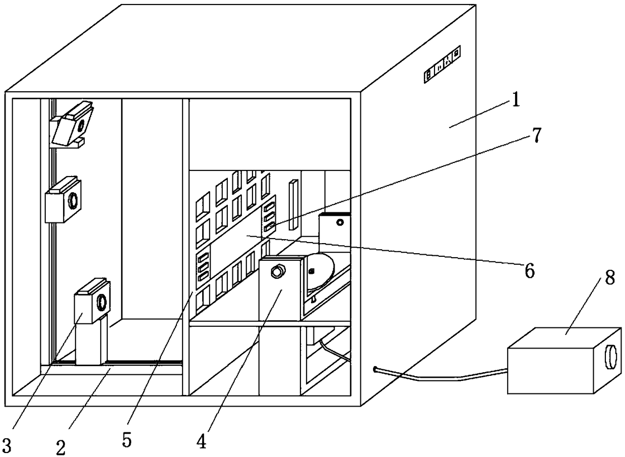
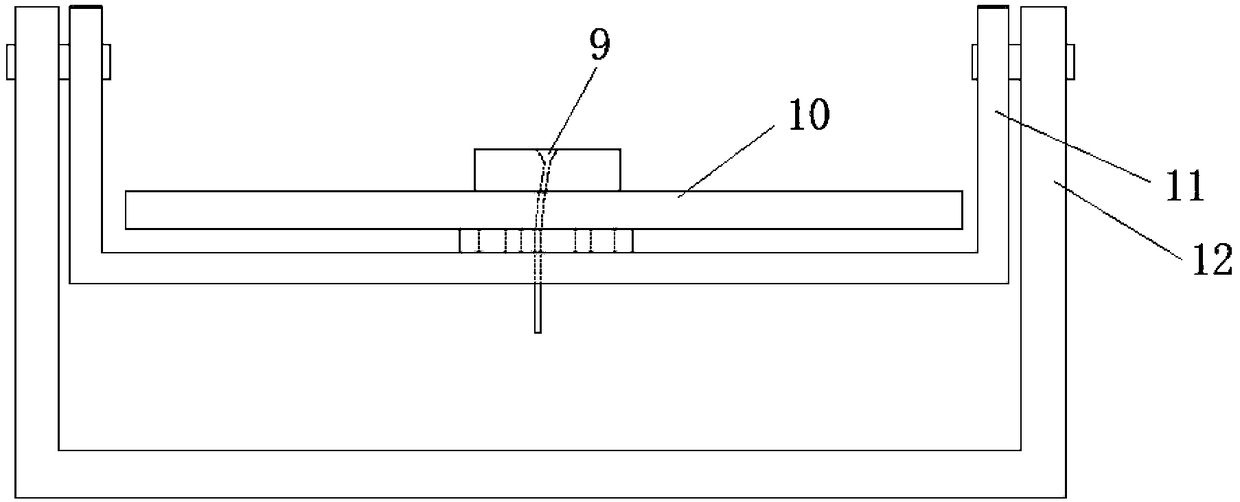
[0024] Such as figure 1 and figure 2 As shown, a shooting box for shooting jewelry includes a box body 1, at least one electric slide rail 2 and a rotatable base 4 are arranged in the box body, and a pedestal for placing jewelry is arranged on the base Groove 9; a camera 3 is installed on the electric slide rail, and the shooting direction of the camera is towards the base; one side and the top of the base are provided with LED7, and the four sides of the base are provided with mirrors for reflecting light. The invention reduces the environmental impact and improves the shooting effect by shooting inside the box; adjusting the position of the base and using a camera with multiple gears, the camera can be displaced through the electric slide rail, which is convenient for changing the position of the jewelry, shooting from different angles, ...


PUM


Abstract

The invention relates to the mechanical field, and specifically relates to a shooting box. The shooting box for shooting jewelry comprises a box body, at least one electric sliding rail and a rotatable base are arranged in the box body; a groove for placing the jewelry is arranged on the base; a camera is arranged on the electric sliding rail, and a shooting direction of the camera is towards thebase; LEDs are arranged at one side and the upper side of the base; and mirrors for reflecting light are arranged at four sides of the base. The different color temperatures can be realized through the LEDs in the box body, the professional environments required for shooting various precious stone and jewelries are created by using the inclination and rotation of the base and the focusing and shooting of the camera, and the shooting effect and the shooting efficiency are improved; the base location is adjusted and the camera with multiple gears is utilized, the camera can displace through theelectric sliding rail so that the camera location can be conveniently changed, the precious stones and jewelries can be shot by changing the angle, so that the shooting difficulty and the shooting cost are reduced, and the average person can simply and conveniently shoot the professional jewelry image.

Description

technical field [0001] The present invention relates to the mechanical field, in particular, to a shooting box. Background technique [0002] Due to the difficulty of shooting jewelry products, professional photographers or outsourcing teams are required to complete them in a professional photography environment. To collect a 360° image of a product requires a professional photographer to work in a professional environment for 1-2 hours to complete a piece. Jewelry or gemstones, the high-definition pictures collected in this way are high in cost and low in efficiency, and there are safety hazards in the shooting process, which are problems to be solved in the jewelry industry. At present, some companies are promoting intelligent image acquisition equipment, but the operation is still complicated, requiring a separate photography environment, which requires high requirements for operators, relatively high equipment costs, and has no obvious advantages compared with traditiona...

Claims


Application Information

Patent Timeline
Patent Type & Authority Applications(China)
IPC IPC(8): G03B15/06G03B15/03G03B17/56
CPCG03B15/03G03B15/06G03B17/561
Inventor 陈家浩
Owner 上海万宝商琏电子商务有限公司
Why Eureka
Try Eureka