Limiting rotating shaft and electronic device

A shaft and position limiting technology, which is applied in the direction of electrical equipment shells/cabinets/drawers, electrical components, casings/cabinets/drawer parts, etc., can solve the problems of no limit, shell cracking, etc. The effect of broken body and simple structure

Active Publication Date: 2018-09-07
BYD CO LTD
View PDF4 Cites 2 Cited by
  • Summary
  • Abstract
  • Description
  • Claims
  • Application Information

AI Technical Summary

Problems solved by technology

[0003] The technical problem to be solved by the present invention is to provide a limited rotating shaft for the defects that the existing rotating shaft with a spring tends to break when the spring force is too large and there is no limit.

Method used


Image

  • Limiting rotating shaft and electronic device
  • Limiting rotating shaft and electronic device
  • Limiting rotating shaft and electronic device

Examples


Embodiment Construction

[0024] Embodiments of the present invention are described in detail below, examples of which are shown in the drawings, wherein the same or similar reference numerals designate the same or similar elements or elements having the same or similar functions throughout. The embodiments described below by referring to the figures are exemplary only for explaining the present invention and should not be construed as limiting the present invention.

[0025] The following disclosure provides many different embodiments or examples for implementing different structures of the present invention. To simplify the disclosure of the present invention, components and arrangements of specific examples are described below. Of course, they are only examples and are not intended to limit the invention. Furthermore, the present invention may repeat reference numerals and / or letters in different instances. This repetition is for the purpose of simplicity and clarity and does not in itself indicat...


PUM


Abstract

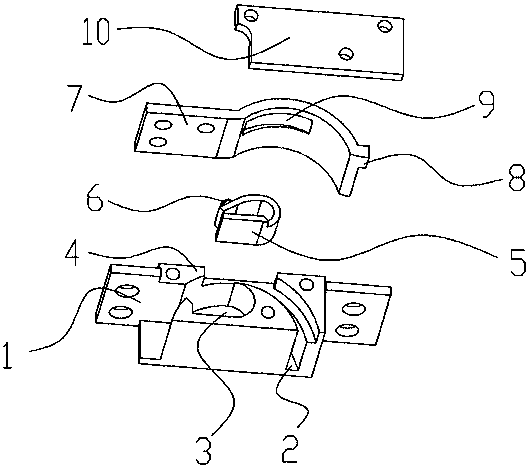
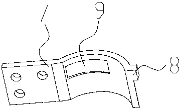
The invention provides a limiting rotating shaft. The limiting rotating shaft comprises a rotating shaft slide block plate, a limiting support block and a supporting base, the rotating shaft slide block plate is provided with a limiting projection, the limiting support block is used to support the rotating shaft slide block plate, the support base is provided with a guide rail groove for accommodating the rotating shaft slide block plate and a limiting block groove for accommodating the limiting support block, the limiting support block supports the rotating shaft slide block plate so that therotating shaft slide block plate slides in the guide rail groove, and the support base is provided with a block in cooperation with the limiting projection on the rotating shaft slide block plate tolimit a rotating shaft. Via the limiting rotating shaft of the invention, a casing is avoided from fracture due to a too large spring force of a present rotating shaft with a spring, and a limiting and fixing effect is provided.

Description

technical field [0001] The invention belongs to the field of connection structures, in particular to a position-limiting rotating shaft. Background technique [0002] The existing rotating shaft is composed of a box, shaft, cam, spring, guide pin and other structures. It connects the flipping structure with the main body and drives through the internal spring and shaft. The product adjusts the spring force to adapt to different torques. need. This type of rotating shaft needs to rely on the spring force to obtain the torsion force, and when the spring force is too large, it is easy to cause the shell to break; during the assembly process, if the rotating shaft is too tightly matched with the flip center shaft, it is easy to cause the flip center shaft to break. After the flip is opened, the angle can continue to increase with force, and no reasonable gear is set to prevent the flip from continuing. Contents of the invention [0003] The technical problem to be solved by ...

Claims


Application Information

Patent Timeline
Patent Type & Authority Applications(China)
IPC IPC(8): H05K5/02
CPCH05K5/0217
Inventor 杨润杰吴云东
Owner BYD CO LTD
Why Eureka
Try Eureka