
Mixing and kneading device for polymer compositions

Inactive Publication Date: 2005-03-24
PONZIELLI GUISEPPE
View PDF4 Cites 14 Cited by
  • Summary
  • Abstract
  • Description
  • Claims
  • Application Information

AI Technical Summary

Benefits of technology

[0019] Typically, rotors of twin-screw processors used for co-rotating operation have the same structures and dimensions but this is not a critical requirement per se but is preferred for practical reasons, such as economy and simplicity.
[0027] Another example of the need to minimize mixing stress (mainly a shear stress) is required when mixing chopped glass strands with polymer melts. Strand filaments are often supplied in small bundles of thousands of chopped glass fibers held together by such additives as silanes normally used as sizing agents etc. For example, bundles of chopped filaments of glass type “E” with a typical average length of 3-4,5 mm or 8-15 mm are commercially sold by major glass fiber manufacturers, and such chopped glass bundles must be subjected to a very small amount of shear stress during mixing so as to avoid glass fiber breakage.
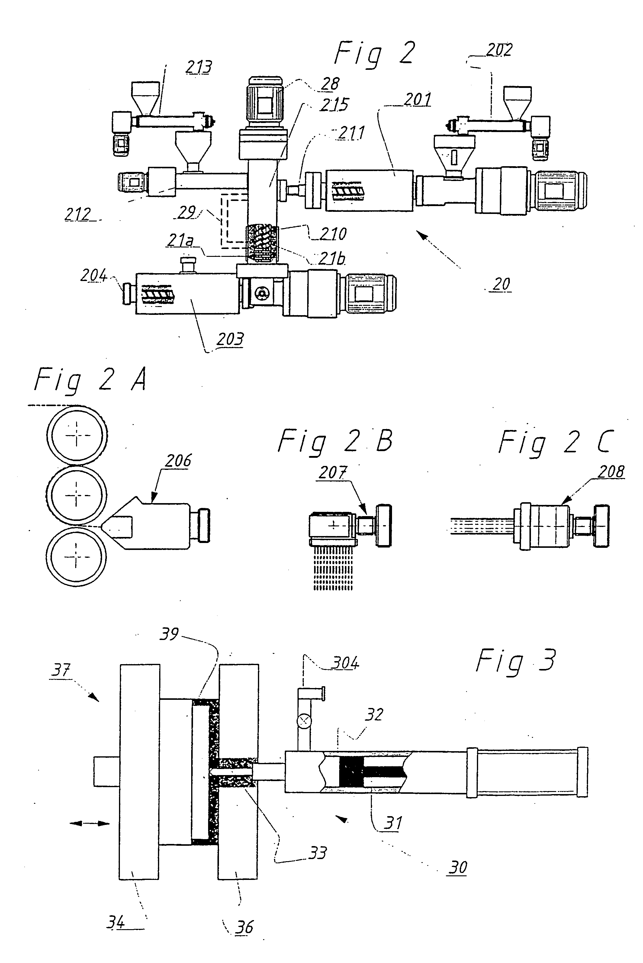
[0039] Again, with reference to an apparatus including a port device positioned between an upstream device for generating a viscous composition that is fed to a port device which, in turn feeds a downstream processor for producing a shaped article, it is preferred that the upstream processor also is a co-rotating twin screw extruder of the high speed type, e.g. capable of operating at speeds of up to 1200 RPM, and dedicated, in essence, to melt or plasticize the polymer to be fed into the port device; this provides an excellent melting rate in the most compact space for maximum process economy when using, for example, small diameter and high speed extruders. As an example, it has been found in the practice of the invention that an upstream co-rotating twin screw extruder of 40 mm diameter and a length of 10-15 diameters used to produce the feed for a port device according to the invention is typically capable of plasticating up to 0,3-0,4 kg per hour per rotation of typical polyolefins so as to yield an output of about 360 kg per hour to 480 kg per hour at 1200 RPM.
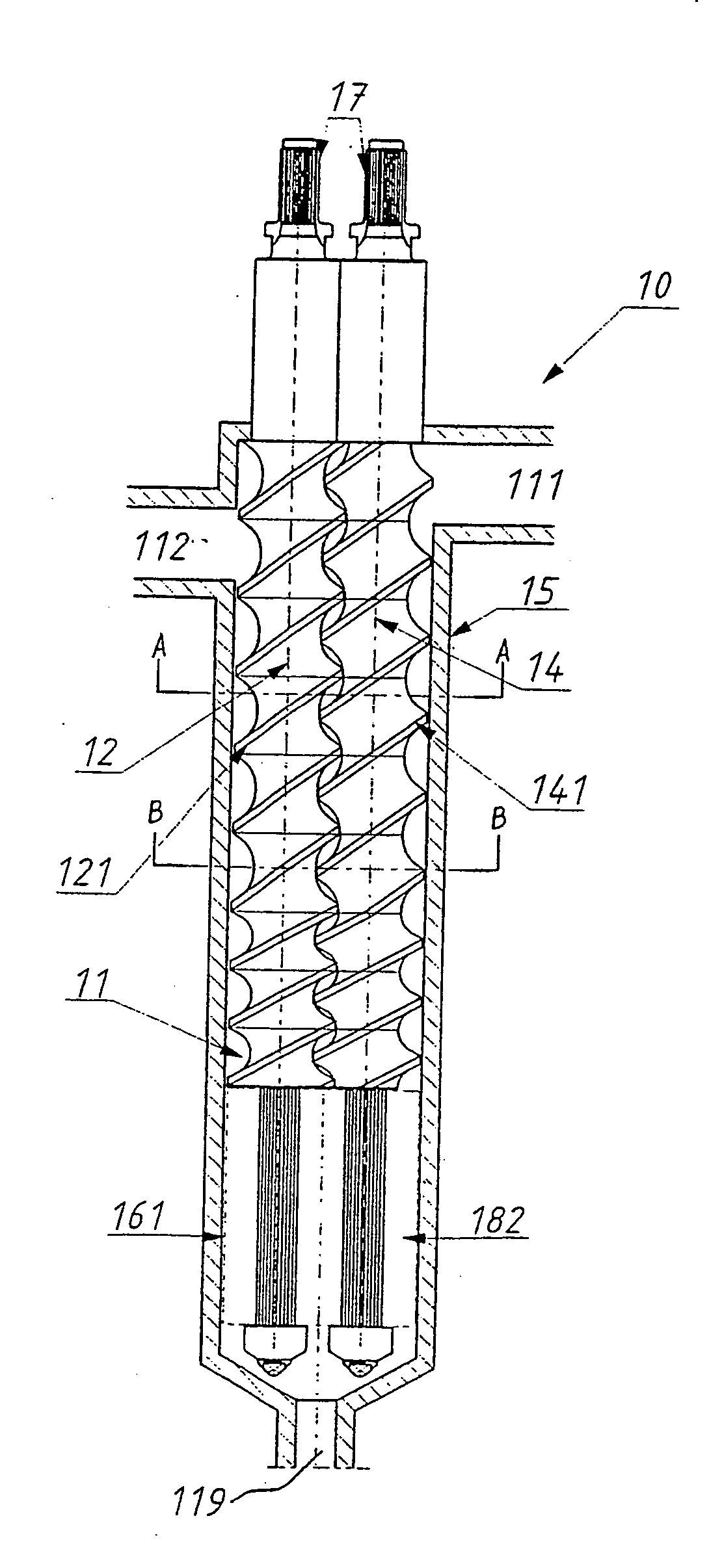
[0042] A port device according to the invention can be operated in various positions from horizontal to vertical as long as gravity does not significantly affect conveying action of the rotors. According to an embodiment preferred for many purposes, the cavity and the rotors of a port device extend in an essentially vertical direction in the sense that material flow through the port will be downward so that gravitation contributes rather than opposes the conveying action of the first flight portions. Vertical design may provide important benefits, such as compact arrange-ment, an advantageous filling rate independently from the rotor's speed, a most effective venting of the melt upstream of the mixing zone and other benefits of vertical orientation.

Problems solved by technology

In fact, many processors of the screw, extruder type are used for this purpose but tend to comminute fragile fillers.
It may happen, however, that such high speed may conflict seriously with the desired quality for several applications, e.g. when a low or a very low processing speed is required to achieve a given quality.
It would not be helpful, however, to use conventional plasticating mixers, such as co-rotating twin screw extruders, and to simply reduce the processing speed because at low or very low speeds melting conditions cannot be achieved.
As known to those skilled in extrusion art, melting of polymers often needs a certain amount of frictional heat developed by the screws upon rotation; however, when operation speed is under a certain critical threshold, not enough frictional heat will be generated by the rotating screws, and not enough thermal energy for melting will be provided by the extrusion system.
In other words, when using a conventional screw extruder where the same shaft effects both plastication and mixing, it will be difficult, at best, to simultaneously achieve an optimum speed for plastication as well as an optimum speed for mixing; this is due to the simple reason that such two optimal speeds will differ.

Method used


Image

  • Mixing and kneading device for polymer compositions
  • Mixing and kneading device for polymer compositions
  • Mixing and kneading device for polymer compositions

Examples


example 1

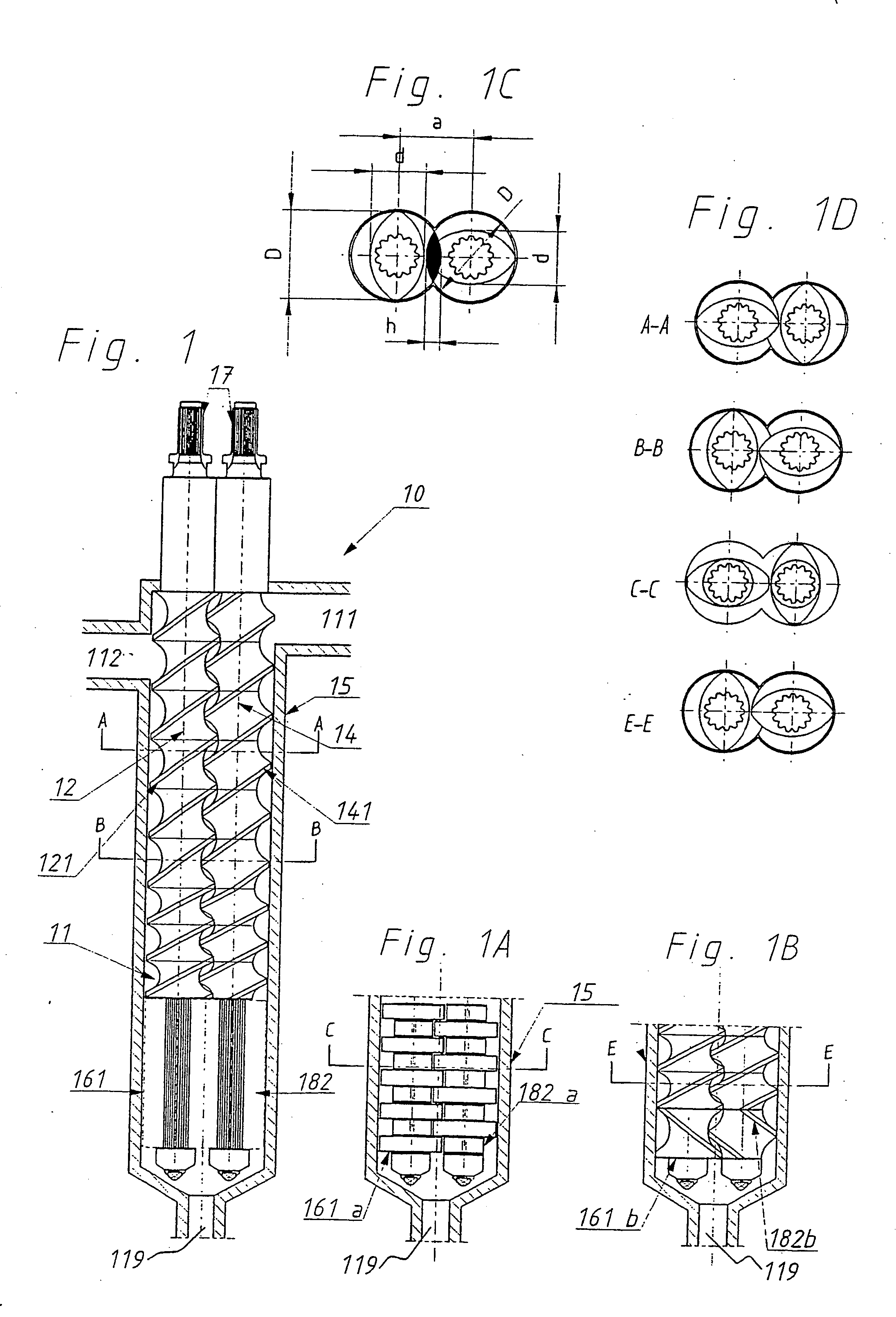
[0073] Recycled polypropylene was plasticated in the upstream processor (screw diameter 45 mm, length 25 D) of an apparatus as shown in FIG. 2 and introduced into the port device (a co-rotating, fully intermeshing self-wiping twin screw; screw diameter 60 mm, length 10D and a non-conveying end portion as shown in 1B) as a plasticated polymer composition under operating conditions for plastication. Chopped glass fibers with an initial length of about 8 to 10 mm were added by a metering device so as to make up about 30% by weight of the final composition that is passed from the port device to the downstream processor and from there into an extrusion head and, further downstream, into a calibration section for producing structural panels having a rigidity of above 7,000 MPa.

example 2

[0074] Commercial linear low density polyethylene (LLDPE) was plasticated in the upstream processor of an apparatus as shown in FIG. 2 and as specified in Example 1 and introduced into the port device (non-conveying end portion as shown in FIG. 1A) as a plasticized polymer composition. Micronized calcium carbonate was added by a metering device so as to make up about 50% by weight of the final composition that is passed from the port device to the downstream processor equipped for producing high filled stretchable film.

[0075] The product film obtained had a very good appearance and was capable of passing water vapor after stretching (up to about 3.5 times its length in unstretched state).

example 3

[0076] A series of tests were made with a port device as shown in FIG. 1 having a D / d ratio (ratio of inner barrel diameter to the same value reduced by twice screw depth) of 1.72 and a vertical arrangement. Different polymer melt compositions were processed at various speeds, residence times and mixing volumes according to the specific task to be achieved. The results are displayed in Table 1.

TABLE 1(Screw diameter 60 mm)FillingAv.Mixingrate inShearaxialMixingtheVolumetricMixingMixerAv. ShearStrainCompCaselengthVolumemixingflow rateThroughputTimespeedRate(StrainarativeNo.(m)(m3)section(m3 / s)(kg / hr)(s)(rpm)(s−1)Units)*strain10.100.0001810.0000029106210 2,5155 120.150.0002710.0000029109410 2,5235 1,5130.200.0003610.00000291012410 2,5310 240.100.0001810.0000029106220 5310 250.100.0001810.0000029106230 7,5465 360.100.0001810.00001462501230 7,590 0,5870.100.0003610.00000291012420050620040

*The actual shear rate was calculated for a screw channel depth of 12,5 mm and the comparative she...


PUM

PropertyMeasurementUnit
Lengthaaaaaaaaaa
Lengthaaaaaaaaaa
Timeaaaaaaaaaa

Abstract

A mixing / kneading device (10) for receiving a viscous composition and for admixing at least one additional constituent therewith, said device comprising: an elongated cavity (11) formed by an enclosure (15) and having a length and a diameter, and including a first inlet (112) for introducing said viscous composition into said device, and at least one second inlet (111) for introducing said at least one 10 additional constituent; and an outlet end (119) downstream of said first and said second inlet for connecting said mixing / kneading device with a processor; a pair of elongated rotors (12,14) for co-rotation within said cavity (11); said elongated rotors each having a first and mutually inter-matching flight portion (121;141) closely fitting into said cavity (11) and being adapted to forcingly convey said viscous composition and said at least one additive distributed therein through said cavity (11) towards said outlet end (119) thereof; and at least one non-conveying portion (161;182) downstream of each of said first portions (121;141) adapted to improve said distribution of said at least one additive in said viscous composition.

Description

BACKGROUND OF THE INVENTION [0001] 1. Field of the Invention [0002] The present invention generally relates to processing of viscous compositions, preferably but not exclusively to plasticated polymer compositions, such as normally solid thermoplastic polymers at extrusion temperatures of typically in the range of from about 150-300° C. [0003] A problem connected with such processing is uniform admixing of various types of additional components or additives with such polymer compositions. Generally, such admixing is effected when the polymer composition is in a plasticated or molten state. However, because of the generally high viscosities of polymer compositions at processing temperatures this is not without problems because fillers, such as glass fillers or fibers, which—while sometimes effective to mechanically reinforce the resulting products—are relatively fragile and tend to become comminuted or excessively disaggregated or disintegrated when exposed to forces generated upon m...

Claims


Application Information

Patent Timeline
IPC IPC(8): B29B7/48B29C48/03B29C48/06B29C48/08B29C48/38B29C48/54B29C48/55B29C48/57
CPCB29B7/487B29C45/1816B29C45/54B29C47/0009B29C47/0016B29C47/0021B29C47/6056B29C47/725B29C2045/466B29K2105/06B29C47/1081B29C47/6031B29C47/6037B29C47/402B29C48/297B29C48/03B29C48/06B29C48/08B29C48/402B29C48/54B29C48/55B29C48/57B29C48/725
Inventor PONZIELLI, GUISEPPE
Owner PONZIELLI GUISEPPE
Learn More