Continuous carbon fiber composite material 3D printing device and method with modifying and dipping synchronization function

A 3D printing and composite material technology, applied in the field of carbon composite fiber 3D printing devices, can solve problems such as inability to eject resin and incomplete combination of model fibers and resin, reduce cost and process complexity, and improve 3D printing quality , improve the effect of the combined effect

Active Publication Date: 2018-08-28
NANJING NORMAL UNIVERSITY +1
View PDF1 Cites 15 Cited by
  • Summary
  • Abstract
  • Description
  • Claims
  • Application Information

AI Technical Summary

Problems solved by technology

Since the continuous carbon fiber and the molten PLA resin cannot be well fused together, the resin cannot be ejected from the nozzle together with the fiber during the printing process, and the printed model fiber is not completely combined with the resin.

Method used


Image

  • Continuous carbon fiber composite material 3D printing device and method with modifying and dipping synchronization function
  • Continuous carbon fiber composite material 3D printing device and method with modifying and dipping synchronization function

Examples


Embodiment 1

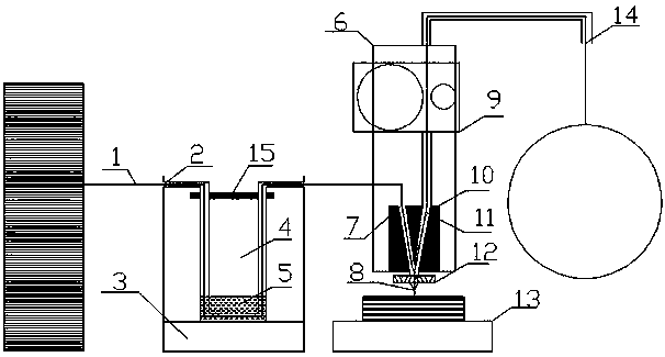
[0029] Example 1: A continuous carbon fiber composite material 3D printing device that can be simultaneously modified and impregnated, such as figure 1 As shown, it includes a synchronous modification container 4, a print head 10, a fiber conduit 2, a resin conduit, a stepping motor 9, a heating block 12 and a copper nozzle 8, and the stepping motor 9 and the print head 10 are fixed on the bracket 6 up and down.

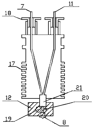
[0030] Among them, such as figure 2 As shown, the print head 10 includes a print head body and two wire feed channels 7, 11 that run through the body longitudinally. There are several layers of horizontal sheet-shaped raised cooling fins 17 . The two wire feeding holes 7 and 11 are left-right symmetrical, the top of the left wire feeding hole 7 is connected to the fiber conduit 2, and the top of the right wire feeding hole 11 is connected to the resin conduit. The resin in the resin conduit is promoted by the stepping motor 9, and the inlet of the right side chann...

Embodiment 2

[0036] Embodiment 2: roughly the same as Embodiment 1, the difference is the configuration of the modified solution, the volume ratio of PLA particles and methylene chloride liquid is 1:8, and the rotation time on the magnetic stirrer is 35min; after printing starts, The heating temperature of the heating block 12 was 225°C.

Embodiment 3

[0037] Embodiment 3: roughly the same as Embodiment 1, the difference is the configuration of the modified solution, the volume ratio of PLA particles and methylene chloride liquid is 1:10, and the rotation time on the magnetic stirrer is 40min; after printing starts, The heating temperature of the heating block 12 was 235°C.


PUM


Abstract

The invention provides a continuous carbon fiber composite material 3D printing device and method with a modifying and dipping synchronization function. A fiber guide pipe is partially immersed in a solution of a synchronous modification container, and the immersed part is provided with a notch for the solution to flow; the fiber guide pipe and a resin guide pipe are connected with two inlets of aprinting head respectively, an outlet of the printing head is connected with a heating block, and a nozzle is arranged at the bottom of the heating block. According to the device and method, 3D printing of the fiber composite material which is synchronously modified and dipped is achieved; through the design of a mechanical structure, the modified continuous fiber enters the heating block along with resin to be printed, the unmodified resin is conveyed into a modification solution to be soaked and modified so that printed carbon fibers can be modified all the time, and synchronization of fiber modification and printing is effectively achieved; after the carbon fibers are soaked with the modified solution, original cellosilk which is easy to disperse in the carbon fibers is combined more tightly; the surfaces of the carbon fibers are coated with a layer of resin, so that the binding effect of the carbon fibers and the resin in the molten state is improved, and the continuous carbon fiber material is not easy to break in the printing process.

Description

technical field [0001] The invention relates to a carbon fiber, in particular to a 3D printing device and method of a carbon composite fiber. Background technique [0002] Fiber-reinforced composite materials have become an important structural material for modern industries, especially aerospace and automotive racing, due to their incomparable advantages in performance (such as light weight, high strength, dimensional stability and good design) that other materials cannot match. [0003] The use of composite parts in aircraft and automobiles can significantly reduce structural weight, which is of great significance for reducing operating costs and improving fuel efficiency and safety. The traditional composite material process has disadvantages such as low degree of automation and long molding cycle, and the productivity is limited by the suppression of low industrial productivity and labor cost. [0004] In recent years, the emergence of three-dimensional (Three dimension...

Claims


Application Information

Patent Timeline
Patent Type & Authority Applications(China)
IPC IPC(8): B29C64/112B29C64/118B29C64/314B33Y30/00B33Y40/00
CPCB33Y30/00B33Y40/00
Inventor 程军韩宁达杨继全刘益剑李宗安李客楼王联凤朱小刚时云刘正武乔凤斌
Owner NANJING NORMAL UNIVERSITY
Why Eureka
Try Eureka