Apparatus and methods of cleaning and refinishing tubulars

a tubular and apparatus technology, applied in the field of apparatus and methods of cleaning and refinishing tubulars, can solve the problems of metal burrs on the inside of the casing around the window, tubular may not fully eliminate all of the metal that comprised the packer, and primarily present problems in paraffin deposits, so as to achieve the effect of altering the surface characteristics

Inactive Publication Date: 2005-02-03
WEATHERFORD TECH HLDG LLC
View PDF25 Cites 17 Cited by
  • Summary
  • Abstract
  • Description
  • Claims
  • Application Information

AI Technical Summary

Benefits of technology

[0013] The present invention generally relates to a method for cleaning and / or altering an inside surface finish and shape of a tubular. The method includes placing a surface finishing tool in the tubular, energizing the tool, and causing extendable assemblies therein to extend radially into contact with an inside diameter of the tubular. Moving the tool axially and / or rotationally while a portion of the extendable assembly is in contact with the inside diameter of the tubular cleans out debris that has collected in the tubular. In another aspect of the invention, the tool burnishes the inside diameter of the tubular, thereby altering the surface characteristics and rounding the tubular.

Problems solved by technology

For example, drilling out a packer in order to remove it from the tubular may not fully eliminate all of the metal that comprised the packer.
Also, milling a window in the casing to run a horizontal bore causes metal burrs on the inside of the casing around the window.
Paraffin deposits primarily present a problem for sub-sea tubulars.
Highly deviated and horizontal bores are particularly susceptible to collecting debris.
Debris that collects on the inside surface of the tubular that defines the bore can obstruct passage through the bore of tubing, equipment, and tools used in various exploration and production operations.
Even if the tool can pass through the bore, debris often causes wear and damage to the tubing, equipment, and tools that pass through it.
Sustaining production rates requires periodic cleaning since deposits and solidified paraffin on the inside of production tubulars slows down production of oil from the well.
Exposure to erosion and corrosion add to the roughness and inconsistent roundness of the inside surface of the tubulars.
Even initially, the inside surface of a tubular is typically rough and inconsistently round.
Fixed diameter reaming members, scrappers, shoes on the end of tubulars, and circulating cleanout fluids do not allow the ability to clean, alter the surface finish, and / or round various sizes of tubulars during one downhole operation.
Additionally, these devices when used downhole for cleaning tubulars require costly and time consuming separate trips downhole to perform multiple operations such as cutting of the tubular or pressure testing within the tubular.

Method used


Image

  • Apparatus and methods of cleaning and refinishing tubulars
  • Apparatus and methods of cleaning and refinishing tubulars
  • Apparatus and methods of cleaning and refinishing tubulars

Examples


Embodiment Construction

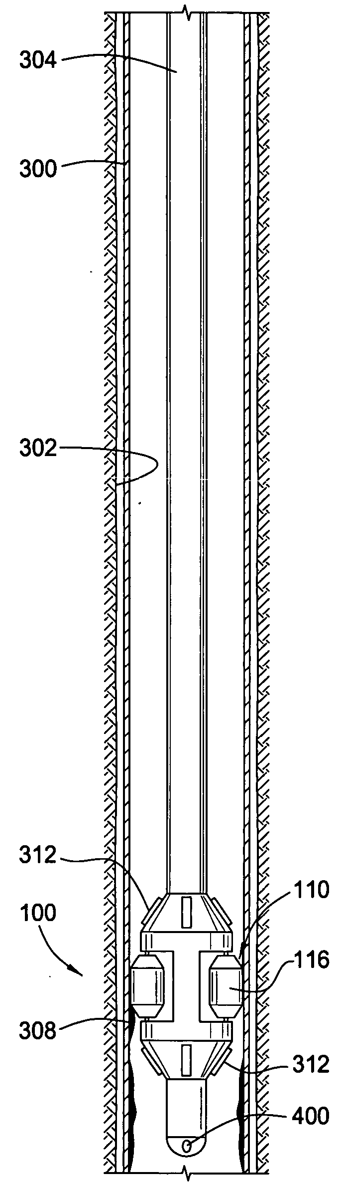
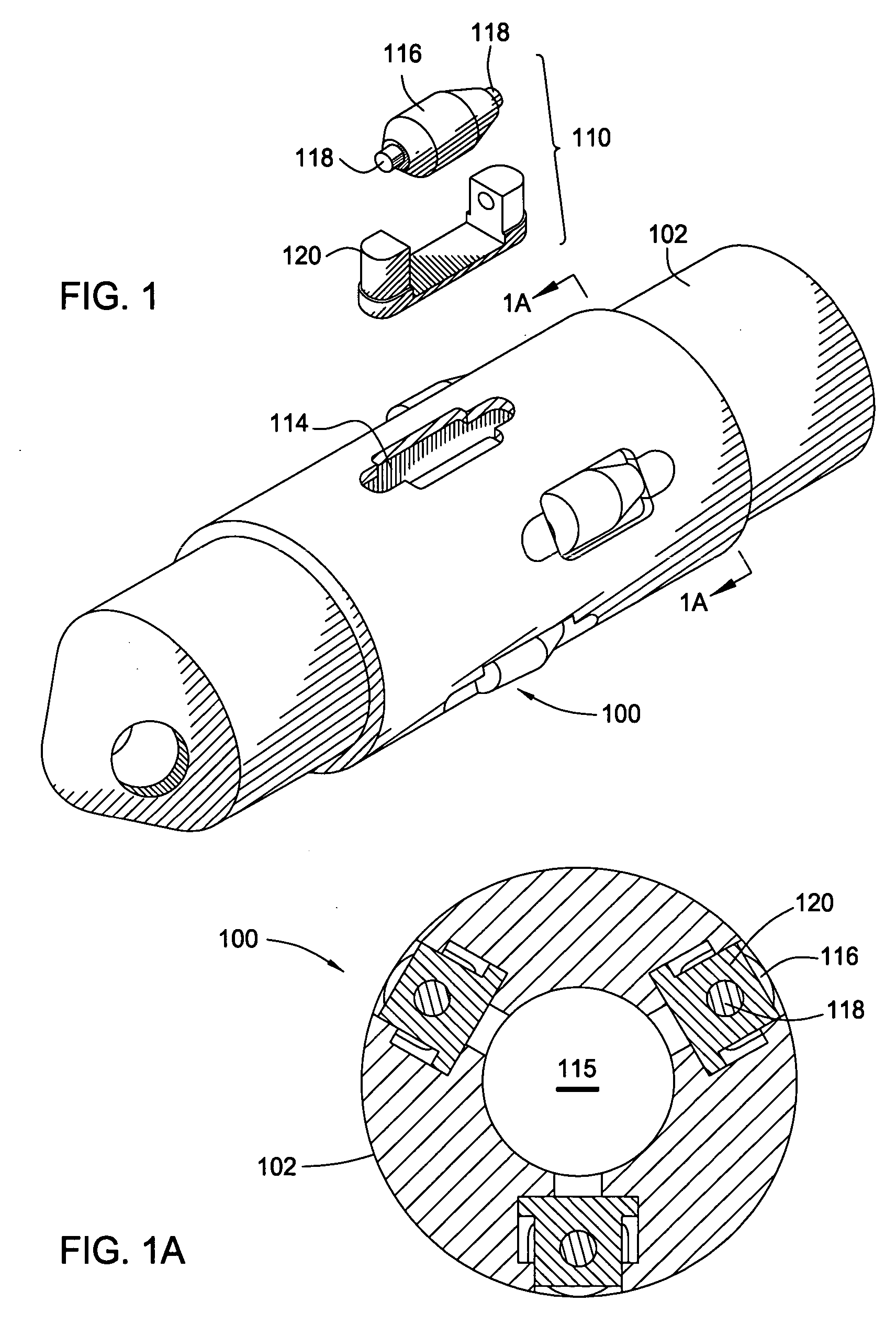
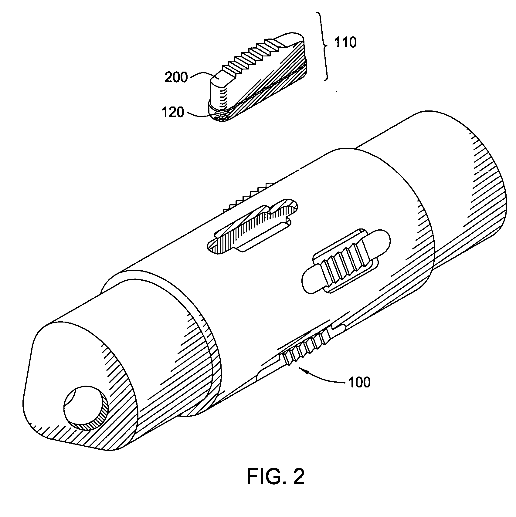
[0027]FIG. 1 shows an exploded view of the surface finishing tool 100 with a body 102 that is hollow and generally tubular. FIG. 1A presents the same surface finishing tool 100 in cross-section, with the view taken across line 1A-1A of FIG. 1. The central body 102 has a plurality of recesses 114 to hold a respective extendable assembly 110. Each of the recesses 114 has substantially parallel sides and holds a respective piston 120. The pistons 120 are radially slidable, one piston 120 being slidably sealed within each recess 114. The backside of each piston 120 is exposed to the pressure of fluid within a hollow bore 115 of the surface finishing tool 100. In this manner, pressurized fluid provided from the surface of the well can actuate the pistons 120 and cause them to extend outwardly.

[0028] Disposed above each piston 120 is a roller 116. In one embodiment of the surface finishing tool 100, the rollers 116 are near cylindrical and slightly barreled. Each of the rollers 116 is su...


PUM


Abstract

A method for cleaning and / or altering an inside surface and shape of a tubular is disclosed. The method includes placing a surface finishing tool in the tubular, energizing the surface finishing tool, and causing extendable assemblies therein to extend radially to contact an inside diameter of the tubular. Moving the surface finishing tool axially and / or rotationally while the extended members are in contact with the inside diameter of the tubular cleans debris from the inside surface of the tubular. In another aspect of the invention, the tool burnishes the inside diameter of the tubular, thereby altering the surface characteristics and rounding the tubular.

Description

CROSS-REFERENCE TO RELATED APPLICATIONS [0001] This application is a continuation-in-part of co-pending U.S. patent application Ser. No. 10 / 222,544, filed Aug. 16, 2002, which is herein incorporated by reference in its entirety.BACKGROUND OF THE INVENTION [0002] 1. Field of the Invention [0003] Embodiments of the present invention generally relate to methods of cleaning scale and deposits and altering the surface and shape of the inside diameter of tubulars. [0004] 2. Description of the Related Art [0005] Hydrocarbon wells typically begin by drilling a borehole from the earth's surface to a selected depth in order to intersect a formation. Steel casing lines the borehole formed in the earth during the drilling process. This creates an annular area between the casing and the borehole that is filled with cement to further support and form the wellbore. Thereafter, the borehole is drilled to a greater depth using a smaller diameter drill than the diameter of the surface casing. A liner...

Claims


Application Information

Patent Timeline
Patent Type & Authority Applications(United States)
IPC IPC(8): E21B29/10E21B37/04
CPCE21B37/04E21B29/10
Inventor MARTIN, BURTHARRALL, SIMON JOHN
Owner WEATHERFORD TECH HLDG LLC
Why Eureka
Try Eureka