Low-range piezoresistive pressure sensor for vacuum measurement and manufacturing method thereof

A pressure sensor and vacuum measurement technology, which is applied in the measurement of fluid pressure, the process for producing decorative surface effects, vacuum gauges, etc., can solve the problems of slow response, easy to be affected by sensor drift, and low precision, so as to prevent damage , to achieve normal pressure storage and overload protection, to meet the effect of low-range measurement

Active Publication Date: 2011-11-30
MEMSENSING MICROSYST SUZHOU CHINA
View PDF6 Cites 15 Cited by
  • Summary
  • Abstract
  • Description
  • Claims
  • Application Information

AI Technical Summary

Problems solved by technology

The inert gas He detection method is limited by its high cost and high energy consumption; the main disadvantage of the resonator Q value detection method is that it is easily affected by sensor drift; the Pirani meter

Method used


Image

  • Low-range piezoresistive pressure sensor for vacuum measurement and manufacturing method thereof
  • Low-range piezoresistive pressure sensor for vacuum measurement and manufacturing method thereof
  • Low-range piezoresistive pressure sensor for vacuum measurement and manufacturing method thereof

Examples


Embodiment Construction

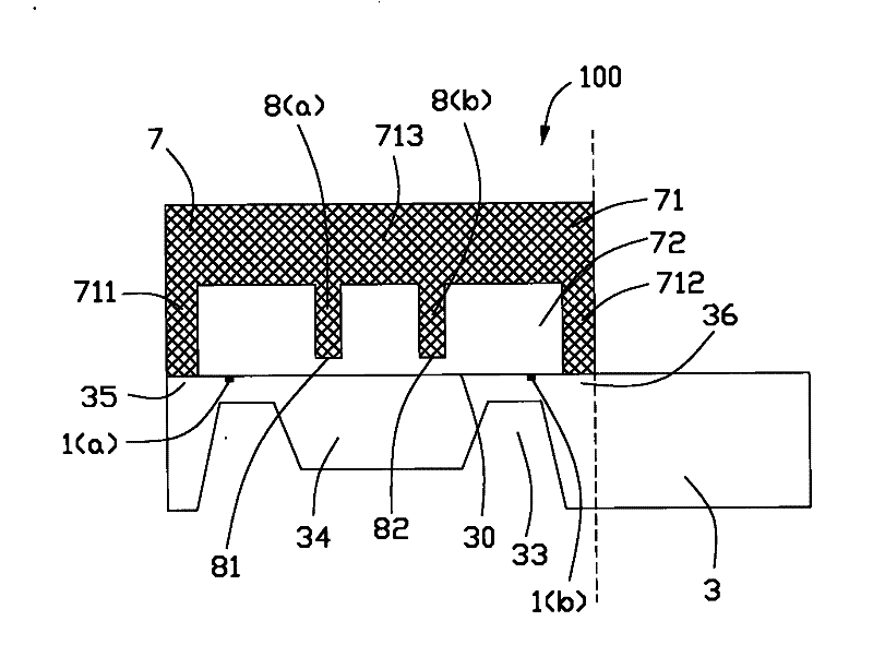
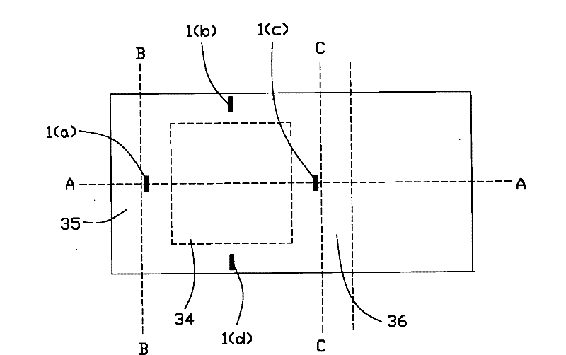
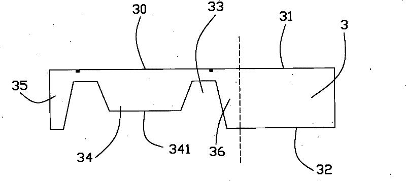
[0030] Please refer to Figure 1 to Figure 3 As shown, the present invention discloses a piezoresistive pressure sensor 100 for vacuum measurement, which includes: a silicon chip 3 and a bonding layer 7 fixed on the silicon chip 3 . The piezoresistive pressure sensor 100 is used to measure absolute pressure under vacuum conditions. The silicon wafer 3 includes a top wall 31 with a pressure sensitive film 30 , a bottom wall 32 opposite to the top wall 31 , and a back cavity 33 formed upwardly from the bottom wall 32 . Please refer to figure 1 As shown, the pressure sensitive film 30 is located between the dotted lines BB and CC.

[0031] The pressure-sensitive film 30 communicates with the back cavity 33 and is located above the back cavity 33. The pressure-sensitive film 30 is distributed with four piezoresistive strips 1(a), 1 connected to form a Wheatstone bridge in its stress concentration area. (b), 1(c), 1(d). The piezoresistive strips 1(a)-1(d) can be made by diffusi...


PUM


Abstract

The invention discloses a method for manufacturing a low-range piezoresistive pressure sensor for vacuum measurement comprising the following steps: (a) providing a silicon wafer, covering a silicon oxide and a silicon nitride as a mask on the back of the silicon wafer, and etching the silicon oxide and silicon nitride as the mask by using RIE to form a membrane structure opening; (b) removing a photoresist and corroding or etching the silicon wafer so as to form a certain depth at the opening of the membrane structure; (c) photoetching an island structure, and etching the silicon oxide and the silicon nitride on the island structure by using RIE; (d) removing the photoresist and keeping on corroding or etching the silicon wafer, obtaining a pressure sensing film with the desired depth; (e) corroding the remaining silicon oxide and silicon nitride by using BOE; (f) providing a bonding layer, and fixing the bonding layer at the front of the silicon wafer, arranging a cavity communicated with the pressure sensing film and a stop block downwardly extending to the cavity on the bonding layer, and reserving a gap between the stop block and the pressure sensing film for limiting excessive deformation of the pressure sensing film; also comprising a step of making a plurality of piezoresistive bars which can connect a Wheatstone bridge at a stress concentration area of the pressure sensing film. The design of the stop block limits the maximum displacement of the pressure sensing film so as to realize the functions of ordinary pressure protection and overload protection of the sensor.

Description

【Technical field】 [0001] The invention relates to a piezoresistive pressure sensor and a manufacturing method thereof, belonging to the field of microelectromechanical system (MEMS) sensors. 【Background technique】 [0002] Silicon pressure sensors are an important part of commercial silicon sensors. According to the working principle, they are mainly divided into piezoresistive, capacitive, and resonant, which has achieved rapid development in recent years. Because microelectromechanical systems (MEMS) technology originated from the development of silicon sensors, it was first used to produce silicon piezoresistive pressure sensors. At present, silicon piezoresistive pressure sensor technology is the most mature and is the mainstream technology in practical products. [0003] The core technology of the silicon piezoresistive pressure sensor lies in the structure and processing technology of the sensing film. Structurally, for the purpose of concentrating stress, membranes ...

Claims


Application Information

Patent Timeline
IPC IPC(8): G01L21/00B81B7/02B81C1/00
Inventor 庄瑞芬李刚
Owner MEMSENSING MICROSYST SUZHOU CHINA
Why Eureka
Try Eureka