Lifting speed bump and traffic control method for road confluence area

A technology of speed bumps and merging areas, which is applied in the field of traffic information engineering and its control, can solve the problems of disorderly order and slow traffic flow in merging areas, and achieve the effects of alleviating driving conditions, reducing the probability of traffic accidents, and improving traffic efficiency

Inactive Publication Date: 2018-09-11
HARBIN INST OF TECH
View PDF6 Cites 4 Cited by
  • Summary
  • Abstract
  • Description
  • Claims
  • Application Information

AI Technical Summary

Problems solved by technology

[0007] The purpose of the present invention is to solve the problem of slow speed and disordered traffic

Method used


Image

  • Lifting speed bump and traffic control method for road confluence area
  • Lifting speed bump and traffic control method for road confluence area
  • Lifting speed bump and traffic control method for road confluence area

Examples


specific Embodiment approach 1

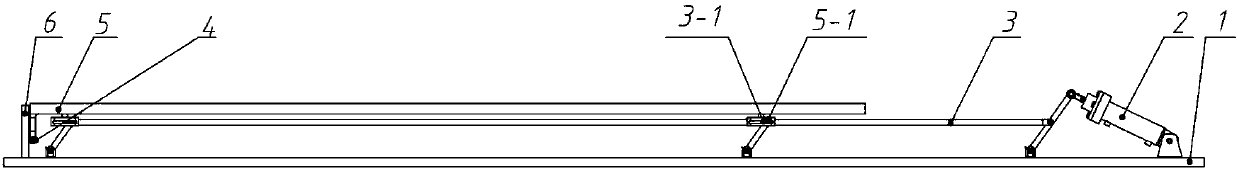
[0027] Specific embodiment 1: A lifting deceleration belt includes: a bottom plate 1, a hydraulic device 2, a planar four-bar mechanism 3, a slider 4, a deceleration belt main body 5 and a guide rail 6;

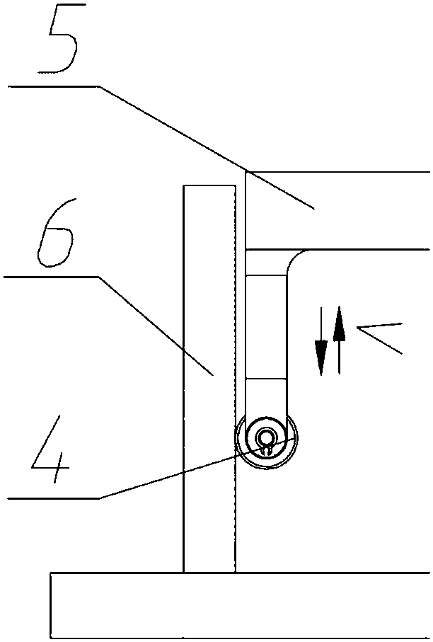
[0028] A hydraulic device 2 is arranged on one end of the surface of the bottom plate 1, and the hydraulic device 2 is connected to the planar four-bar mechanism 3; a guide rail 6 is arranged on the other end of the surface of the bottom plate 1, and the slider 4 is connected to the support rod on the lower surface of the speed reduction belt main body 5, and the slider 4. Move up and down along the guide rail 6, and the speed bump main body 5 is set above the plane four-bar mechanism 3;

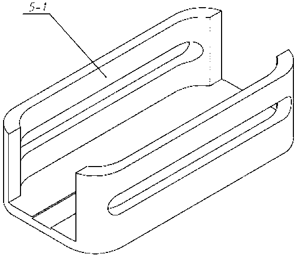
[0029] The lower surface of the deceleration strip main body 5 is provided with a roller guide groove 5-1, and a roller device 3-1 is arranged on the plane four-bar mechanism 3, and the roller device 3-1 is used in conjunction with the roller guide groove 5-1 to realize the horizontal direct...

specific Embodiment approach 2

[0038] Embodiment 2: This embodiment differs from Embodiment 1 in that: the upper surface of the deceleration belt main body 5 is an upwardly protruding curved surface, and the cross section of the deceleration belt main body 5 is in the shape of a inferior arc. The length of the bottom plate 1 is greater than the length of the speed bump main body 5 .

[0039] Other steps and parameters are the same as those in Embodiment 1.

specific Embodiment approach 3

[0040] Embodiment 3: This embodiment differs from Embodiment 1 or Embodiment 2 in that: the length of the deceleration strip main body 5 is the width of a road single lane.

[0041] Other steps and parameters are the same as those in Embodiment 1 or Embodiment 2.


PUM

PropertyMeasurementUnit
Widthaaaaaaaaaa

Abstract

The invention relates to a lifting speed bump and a traffic control method for a road confluence area. The lifting speed bump and the traffic control method for the road confluence area aim at solvingthe problems that the confluence area is low in traffic flow speed and disorderly. The lifting speed bump comprises a base plate, a hydraulic device, a planar four-rod mechanism, a sliding block, amain speed bump body and a guide rail; one end of the surface of the base plate is provided with the hydraulic device, and the hydraulic device is connected with the planar four-rod mechanism; the other end of the surface of the base plate is provided with the guide rail, the sliding block is connected with a supporting rod on the lower surface of the main speed bump body and slides along the guide rail up and down, and the main speed bump body is arranged on the planar four-rod mechanism; the lower surface of the main speed bump body is provided with idler wheel guide grooves, idler wheel devices are arranged on the planar four-rod mechanism and cooperate with the idler wheel guide grooves for use, and the planar four-rod mechanism transversely moves to drive the main speed bump body to move up and down along the guide rail under the function of the sliding block. The lifting speed bump is used in the field of traffic information engineering and control thereof.

Description

technical field [0001] The invention relates to the field of traffic information engineering and its control, in particular to a traffic control method for a lifting speed bump and a road merge area. Background technique [0002] In the urban traffic system, the traffic capacity of the road merging area is one of the important factors affecting the road traffic capacity. However, in the existing urban road system, there are a large number of diverging and merging intersections without corresponding traffic management and control facilities. During the evening rush hour, the number of vehicles weaving and changing lanes in the diverging and merging areas increases, making the diverging and merging areas a "bottleneck" and causing traffic congestion. [0003] At present, the "zipper" traffic regulations implemented in the country at the peak of the merge area: "When two lanes merge into one lane and there is a parking queue or slow driving, pass a car on the left, pass a car o...

Claims


Application Information

Patent Timeline
IPC IPC(8): E01F9/529E01F13/04
CPCE01F9/529E01F13/048
Inventor 章锡俏杨龙海王刚王宇隋孟霖宋浩然陈子杰
Owner HARBIN INST OF TECH
Why Eureka
Try Eureka