Indoor light illuminating and decorating system and method

A lighting and light technology, applied in lighting devices, lighting devices, fixed lighting devices, etc., can solve the problems of complicated construction, dim light, high cost, etc., and achieve the effect of simplifying construction steps and reducing costs

Pending Publication Date: 2018-09-11
明海燕
View PDF0 Cites 0 Cited by
  • Summary
  • Abstract
  • Description
  • Claims
  • Application Information

AI Technical Summary

Problems solved by technology

[0003] For indoor lighting, it is generally realized by installing lighting fixtures on the indoor roof, such as ceiling lights, chandeliers, LED light bars, etc. When working, the lighting fixtures are energized to emit light, and the lighting light is directed from top to bottom. Irradiate into the house to achieve the effect of lighting, but this kind of lighting fixture only has the function of lighting, and generally does not contribute to the rendering of lighting decoration
[0004] For indoor lighting decoration and light tube rendering, it is generally realized by hanging light boxes on the roof. After passing through the lower cover of the light box, it shines into the house. Although this kind of lighting decoration light box has the effect of lighting decoration rendering, but because the light it irradiates is relatively dim and colorful, it generally does not have the lighting effect.
[0005] As mentioned above, if it is necessary to carry out lighting and lighting decoration at the same time indoors, the traditional method is to install lighting fixtures and lighting decoration lighting fixtures on the indoor roof at the same time to achieve the functions of lighting and lighting decoration, but this method not only costs It is expensive, and at the same time, the construction is relatively complicated, and there are many kinds of auxiliary accessories such as switches and circuits, which are the main shortcomings of traditional technologies.

Method used


Image

  • Indoor light illuminating and decorating system and method
  • Indoor light illuminating and decorating system and method
  • Indoor light illuminating and decorating system and method

Examples


Embodiment Construction

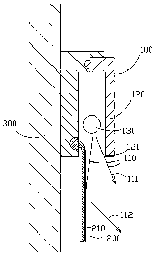
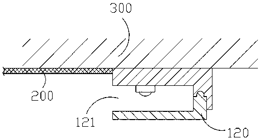
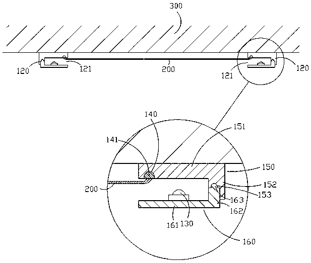
[0026] Such as Figures 1 to 3 As shown, an indoor lighting and decoration system includes a light generating unit 100 and a decoration unit 200 .

[0027] The light generating unit 100 generates light 110 , a part of the light 110 is directly irradiated into the room to form a light 111 for illumination.

[0028] Another part of the light 110 is first irradiated on the surface of the decoration unit 200 , and then reflected and irradiated into the interior to form the light 112 for decoration.

[0029] That is to say, the light generating unit 100 of the present invention can generate the lighting light 111 and the decoration light 112 at the same time, and can effectively integrate traditional lighting fixtures and lighting decoration lighting fixtures, thereby reducing costs and simplifying construction steps. role.

[0030] The light generating unit 100 includes a fixed frame 120 and a light source 130 , the light source 130 is disposed in the fixed frame 120 , and the f...


PUM


Abstract

The invention discloses an indoor light illuminating and decorating system and method. The light illuminating and decorating system comprises a light ray generating unit and a decorating unit. The light ray generating unit generates light rays. One part of the light rays directly irradiate to the indoor space to form illuminating light rays, and the other part of the light rays irradiate to the surface of the decorating unit and then are reflected to irradiate to the indoor space to form decorating light rays. The light ray generating unit of the light illuminating and decorating system can generate the illuminating light rays and the decorating light rays simultaneously, a traditional illuminating lamp and light decorating lamp can be integrated effectively, and accordingly, the effects of reducing the cost and simplifying the construction steps are achieved.

Description

technical field [0001] The invention relates to a lighting and decoration system and a lighting and decoration method thereof, in particular to a lighting and decoration system and a method for integrating lighting lamps and lighting decoration lamps. Background technique [0002] As we all know, the lighting and decorative effects of lights play an irreplaceable role in interior decoration. It not only plays the role of lighting, but also plays the role of increasing or adjusting colors. Its significance lies in beautifying the decorative effect, while achieving certain lighting effect. [0003] For indoor lighting, it is generally realized by installing lighting fixtures on the indoor roof, such as ceiling lights, chandeliers, LED light bars, etc. When working, the lighting fixtures are energized to emit light, and the lighting light is directed from top to bottom. Irradiate into the house to achieve the effect of lighting, but this kind of lighting fixtures only have the...

Claims


Application Information

Patent Timeline
IPC IPC(8): F21S8/00F21V17/10F21V19/00F21V33/00
CPCF21S8/00F21V17/10F21V19/00F21V33/00
Inventor 明海燕
Owner 明海燕
Why Eureka
Try Eureka