Step transition of a rectangular waveguide transmission line

A rectangular waveguide and transmission line technology, applied in the field of electromagnetic wave structure, can solve the problems of complex matching circuit structure, large volume and narrow bandwidth, and achieve obvious advantages and improve computing efficiency.

Inactive Publication Date: 2018-09-11
成都锐烽特科技有限公司
View PDF3 Cites 2 Cited by
  • Summary
  • Abstract
  • Description
  • Claims
  • Application Information

AI Technical Summary

Problems solved by technology

[0003] The existing matching circuit has complex structure, large volume, and narrow bandwidth, especially in rectangular waveguides, single-ridge rectangular waveguides, double-ridge rectangular waveguides and four-ridge rec

Method used


Image

  • Step transition of a rectangular waveguide transmission line
  • Step transition of a rectangular waveguide transmission line
  • Step transition of a rectangular waveguide transmission line

Examples


Example Embodiment

[0040] Implementation Example 1

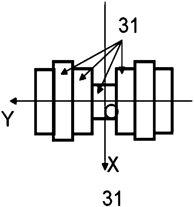
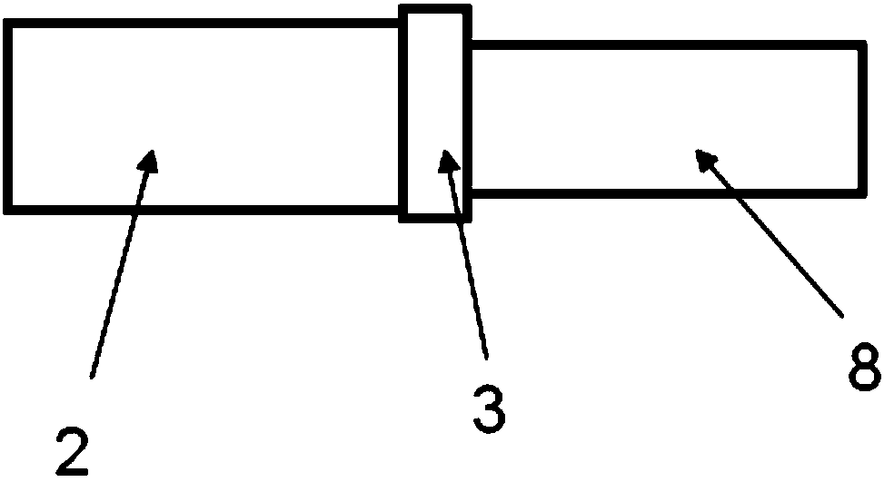
[0041] like Figure 1a , Figure 1b and figure 2 shown.

[0042] A rectangular waveguide transmission line step transition, comprising an input transmission line 2, an output transmission line 8, and an electromagnetic channel 3; the two ends of the electromagnetic channel 3 are respectively a part of a plane A and a plane B; the input transmission line 2 and The output transmission lines 8 respectively communicate with one of the two end faces of the electromagnetic channel 3 through one of its cross sections; the electromagnetic channel 3 is constituted by at least one electromagnetic wave branch. The electromagnetic wave branch is composed of seven through holes 31 that communicate along the Y direction.

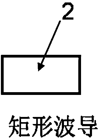
[0043] The input transmission line 2 and the output transmission line 8 have similar cross-sections. That is, the same number of variables are required to describe the cross-sectional shape of the input transmission line 2 and the ou...

Example Embodiment

[0052] Implementation Example 2

[0053] like Figure 1a , Figure 1b and image 3 shown.

[0054] Compared with Embodiment 1, the main difference of this embodiment is only that the input transmission line 2 is a single-ridge rectangular waveguide

Example Embodiment

[0055] Implementation Example 3

[0056] As shown in Figures 1 and 4.

[0057] Compared with Embodiment 1, the main difference of this embodiment is only that the input transmission line 2 is a double-ridged rectangular waveguide.


PUM


Abstract

The invention discloses a step transition of a rectangular waveguide transmission line, which comprises an input transmission line, an output transmission line and at least one electromagnetic channel. The two end surfaces of the electromagnetic channel are part of a plane A and a plane B respectively. The plane A is parallel to the plane B. The input transmission line and the output transmissionline are respectively communicated with one of the two end faces of the electromagnetic channel through one cross section. The input transmission line and the output transmission line are different insize. The input transmission line is a rectangular waveguide. The electromagnetic channel is composed of at least one branch, and at least one electromagnetic wave branch is composed of at least three through holes which are communicated along the Y direction. The transmission line step transition can achieve broadband compact matching transition between transmission lines of different sizes. Thesystem is mainly applied to various communication and radar systems of microwave, millimeter wave and terahertz wave bands.

Description

technical field [0001] The present invention relates to an electromagnetic wave element, in particular to an electromagnetic wave structure that enables a transmission line to be matched and communicated with another transmission line with a different size within a very short distance. Background technique [0002] In various electromagnetic wave systems, connections between similar transmission lines of different sizes are ubiquitous. Signals in the transmission line will be reflected due to the parasitic effects of the discontinuity at the connection. In order to realize the matching of the step transition of the transmission lines, it is necessary to set a matching structure between the transmission lines. [0003] The existing matching circuit has complex structure, large volume, and narrow bandwidth, especially in rectangular waveguides, single-ridge rectangular waveguides, double-ridge rectangular waveguides and four-ridge rectangular waveguides, circular waveguides o...

Claims


Application Information

Patent Timeline
IPC IPC(8): H01P5/02
CPCH01P5/022
Inventor 王清源胡倚铭
Owner 成都锐烽特科技有限公司
Why Eureka
Try Eureka