A three-phase three-level inverter based on switched capacitors

A technology of three-level inverters and switched capacitors, which is applied to electrical components, output power conversion devices, and conversion of AC power input to DC power output. It can solve the problem of voltage imbalance without capacitors and DC bus capacitor voltage imbalance , Capacitor voltage imbalance and other issues

Active Publication Date: 2020-07-07
NANJING UNIV OF SCI & TECH
View PDF3 Cites 0 Cited by
  • Summary
  • Abstract
  • Description
  • Claims
  • Application Information

AI Technical Summary

Problems solved by technology

The voltage stress of the power switch in the diode-clamped three-level topology is half of the DC bus voltage, and the number of capacitors is small, but there is a problem of unbalanced DC bus capacitor voltage
Compared with the diode-clamped three-level inverter, the T-type three-level inverter has six less clamping diodes, and the topology is relatively simple. However, the voltage stress of the switching tube is inconsistent, and there is also the problem of capacitor voltage imbalance.
Capacitor-clamped multilevel converter topology As the number of levels increases, the number of required capacitors increases, and it is difficult to balance the voltage across the clamp capacitors
[0003] Switched capacitor multilevel inverters can use fewer devices to obtain a level that is twice the input voltage, and there is no problem of capacitor voltage imbalance. In recent years, it has received extensive attention at home and abroad, but it is mostly used in single-phase low-power inverters. Occasions, it is rare to use in three-phase output occasions

Method used


Image

  • A three-phase three-level inverter based on switched capacitors
  • A three-phase three-level inverter based on switched capacitors

Examples


Embodiment 1

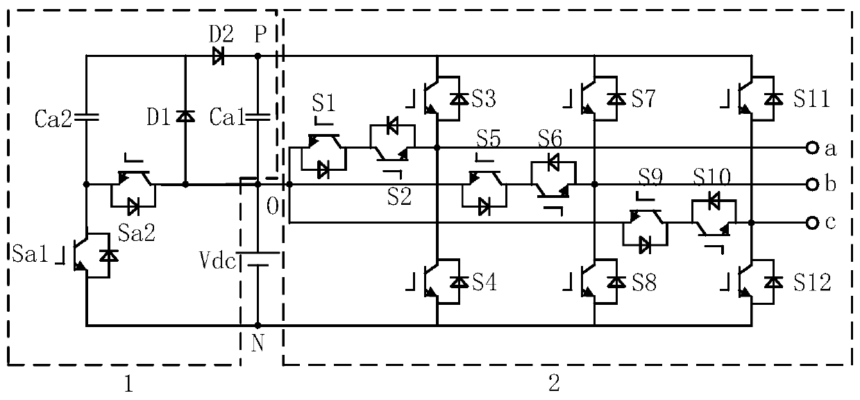
[0025] The first structure of the capacitor voltage stabilizing unit 1 is specifically as follows:

[0026] Including a first capacitor Ca1, a second capacitor Ca2, a first power switch tube Sa1, a second power switch tube Sa2, a first diode D1, and a second diode D2; the cathode of the first capacitor Ca1 is connected to the power supply The anode of Vdc, the connection point is marked as O; the anode of the first capacitor Ca1 is connected to the cathode of the second diode D2, and the connection point is marked as P; the anode of the second diode D2 is connected to the first diode D1 Cathode; the anode of the first diode D1 is connected to the connection point O; the anode of the second capacitor Ca2 is connected to the cathode of the first diode D1; the cathode of the second capacitor Ca2 is connected to the collector of the first power switch Sa1 The emitter of the first power switch Sa1 is connected to the negative pole of the power supply Vdc, and the connection point is m...

Embodiment 2

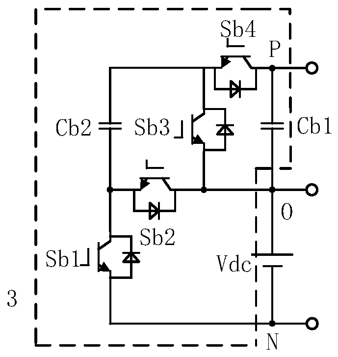
[0028] Combine figure 2 , The second structure of the capacitor voltage stabilization unit 1 includes a third capacitor Cb1, a fourth capacitor Cb2, a third power switch tube Sb1, a fourth power switch tube Sb2, a fifth power switch tube Sb3, and a sixth power switch tube Sb4 . The details are as follows: the negative pole of the third capacitor Cb1 is connected to the positive pole of the power supply Vdc, and the connection point is denoted as O; the positive pole of the third capacitor Cb1 is connected to the collector of the sixth power switch Sb4, and the connection point is denoted as P; The emitter of the power switch tube Sb4 is connected to the collector of the third power switch tube Sb3; the emitter of the fifth power switch tube Sb3 is connected to the connection point O; the anode of the fourth capacitor Cb2 is connected to the emission of the sixth power switch tube Sb4 The cathode of the fourth capacitor Cb2 is connected to the collector of the third power swit...

Embodiment 3

[0030] Combine figure 1 , The output unit 2 adopts a T-type three-phase three-level inverter structure, including the seventh power switch S1, the eighth power switch S2, the ninth power switch S3, the tenth power switch S4, and the eleventh power switch. Switch S5, Twelfth Power Switch S6, Thirteenth Power Switch S7, Fourteenth Power Switch S8, Fifteenth Power Switch S9, Sixteenth Power Switch S10, Seventeenth Power Switch S11, the eighteenth power switch S12;

[0031] The emitter of the seventh power switch S1 is connected to the connection point O; the collector of the seventh power switch S1 is connected to the collector of the eighth power switch S2; the emitter of the eighth power switch S2 is connected to the ninth The emitter of the power switch S3 is connected, and the connection point is marked as the a-phase AC output terminal; the collector of the ninth power switch S3 is connected to the connection point P; the collector of the tenth power switch S4 is connected to t...


PUM


Abstract

The invention discloses a three-phase three-level inverter based on a switched capacitor. The inverter includes a capacitor voltage stabilizing unit and an output unit, wherein the capacitor voltage stabilizing unit generates a capacitor voltage equal to an input voltage, the capacitor voltage and the input voltage are connected in series and superposed to generate a direct current three-level voltage, and the capacitor voltage stabilizing unit may have two different forms; and the output unit performs inversion of the direct current three-level voltage generated by the capacitor voltage stabilizing unit into a required three-phase alternating voltage, and a T type three-phase three-level inverter structure or diode clamping type three-phase three-level converter structure is adopted. Thethree-phase three-level inverter based on a switched capacitor can realize bus capacitor voltage self balancing, reduce resource occupation of a controller, and can reduce output harmonic content, andthe highest amplitude of an output alternating current phase voltage can be two times that of an input direct voltage.

Description

Technical field [0001] The invention belongs to the technical field of power electronic inverters, in particular to a three-phase three-level inverter based on switched capacitors. Background technique [0002] In terms of high-voltage and high-power inverters, traditional two-level voltage source inverters are no longer applicable due to the withstand voltage problems of power devices. In recent years, three-level inverters have been widely used in medium, high voltage and large capacity occasions with their unique structural advantages. The most common three-level inverter topologies can be divided into diode-clamped three-level inverters, T-type three-level inverters, and capacitor-clamped three-level inverters. The voltage stress of the power switch in the diode-clamped three-level topology is half of the DC bus voltage, and the number of capacitors is small, but there is a problem of unbalanced DC bus capacitor voltage. Compared with the diode-clamped three-level inverter,...

Claims


Application Information

Patent Timeline
Patent Type & Authority Patents(China)
IPC IPC(8): H02M7/483
CPCH02M7/483
Inventor 李福印李磊郭志刚管月陆佳炜李广强
Owner NANJING UNIV OF SCI & TECH
Why Eureka
Try Eureka