Spindle structure on precision grinder

A precision grinding machine and spindle technology, applied in the mechanical field, can solve the problem that the grinding effect of the dynamic and static pressure spindle cannot meet the requirements of the roll grinder.

Inactive Publication Date: 2018-09-14
宁波赫力奥斯机电设备有限公司
View PDF1 Cites 1 Cited by
  • Summary
  • Abstract
  • Description
  • Claims
  • Application Information

AI Technical Summary

Problems solved by technology

As users have higher and higher requirements for the surface quality of the plate, the grinding effect of the original dynamic and static pressure spindle used by the roll grinder is increasingly unable to meet the requirements of the roll grinder user.

Method used


Image

  • Spindle structure on precision grinder
  • Spindle structure on precision grinder
  • Spindle structure on precision grinder

Examples


Embodiment Construction

[0012] The following are specific embodiments of the present invention in conjunction with the accompanying drawings to further describe the technical solutions of the present invention, but the present invention is not limited to these embodiments.

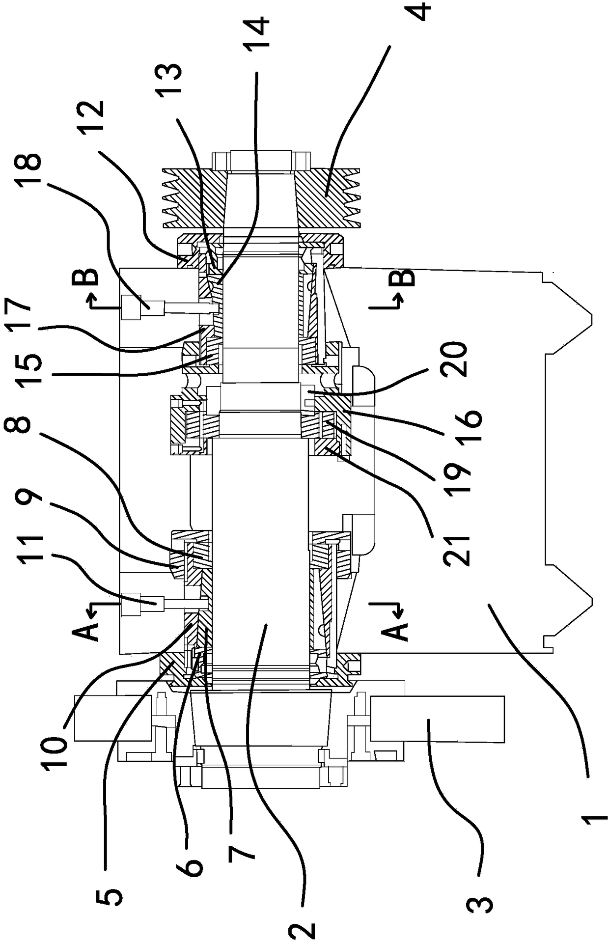
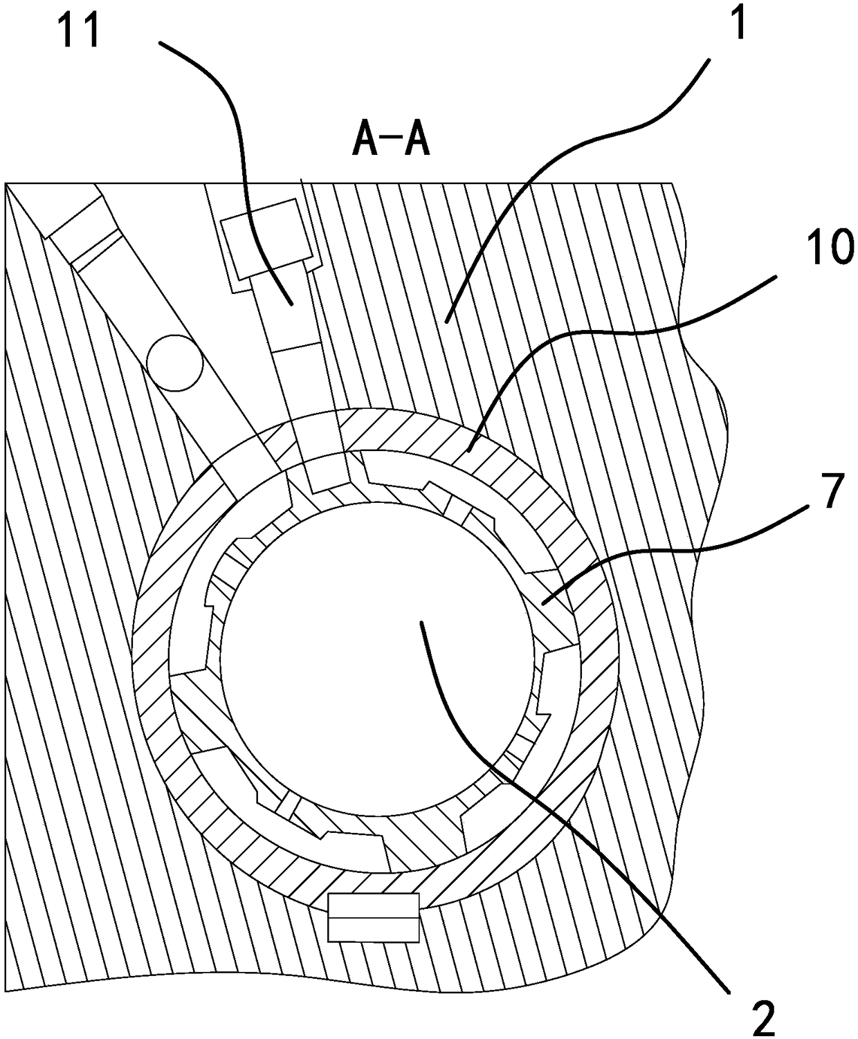
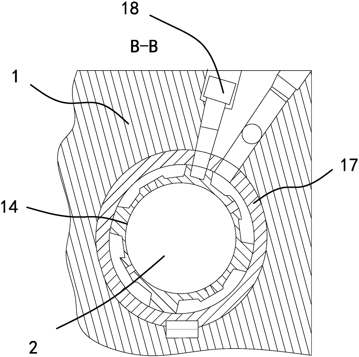
[0013] Such as Figure 1 to Figure 3 As shown, the main shaft structure of the precision grinder is set on the grinding wheel frame 1, including the main shaft 2. The left end of the main shaft 2 is connected with a grinding wheel 3, the right end of the main shaft 2 is connected with a pulley 44, and the left end of the main shaft 2 is installed from left to right. The main lock nut 5, the left main retaining ring 6, the left bearing bush 7 with an outer cone, the left auxiliary retaining ring 8 and the left auxiliary lock nut 9, the two ends of the left bearing 7 abut on the left main retaining ring 6 and the left Between the auxiliary retaining rings 8, the left main lock nut 5 and the left auxiliary lock nut 9 are threadedly con...


PUM


Abstract

The invention provides a spindle structure on a precision grinder, and belongs to the technical field of machines. The problem that an existing dynamic and static pressure spindle is poor in grindingeffect is solved. The spindle structure on the precision grinder is arranged on a grinding wheel frame, a spindle is included, the left end of the spindle is connected with a grinding wheel, the rightend of the spindle is connected with a belt wheel, a left main locking nut, a left main check ring, a left bearing bush with an outer conical face, a left auxiliary check ring and a left auxiliary locking nut are arranged at the left end of the spindle, a left shaft sleeve with an inner conical face is in threaded connection between the left main locking nut and the left auxiliary locking nut, the left bearing bush is fixedly connected with the left shaft sleeve through a left positioning screw, a right locking nut, a right main check ring, a right bearing bush with an outer conical face, a right auxiliary check ring and a thrust locking nut are arranged at the right end of the spindle, a right shaft sleeve with an inner conical face is in threaded connection between the right locking nutand the thrust locking nut, and the right bearing bush and the right shaft sleeve are fixedly connected through a right positioning screw. The spindle structure has the beneficial effects of being high in rigidity, and small in offset during grinding of the spindle center.

Description

Technical field [0001] The invention belongs to the technical field of machinery, and specifically relates to a spindle structure on a precision grinder. Background technique [0002] Roll grinders mainly serve steel, aluminum plants, non-ferrous metals, aluminum foil and paper industries. Almost all manufacturers involved in rolls use roll grinders. As users have higher and higher requirements for the surface quality of the plate, the grinding effect of the original dynamic and static pressure spindle of the roll grinder is less and less than the use requirements of the roll grinder. Summary of the invention [0003] The purpose of the present invention is to solve the above-mentioned problems in the prior art, and propose a spindle structure with high rigidity and small deviation of the spindle center during grinding. [0004] The objective of the present invention can be achieved by the following technical solutions: a spindle structure on a precision grinder, which is arranged ...

Claims


Application Information

Patent Timeline
Patent Type & Authority Applications(China)
IPC IPC(8): B24B41/04
Inventor 王翀
Owner 宁波赫力奥斯机电设备有限公司
Why Eureka
Try Eureka