
A spool, valve and method using the spool

A valve core and valve technology, applied in valve operation/release devices, valve details, valve devices, etc., can solve the problem of impurities or microorganisms entering between the valve ball and the valve body, accelerating the wear of the valve ball and the inner wall of the valve, Reduce the problem of sealing, achieve the effect of convenient precise control, avoid misoperation, and facilitate the flow rate

Active Publication Date: 2021-06-01
WENZHOU ZHENHONG VALVE BALL CO LTD
View PDF0 Cites 0 Cited by
  • Summary
  • Abstract
  • Description
  • Claims
  • Application Information

AI Technical Summary

Problems solved by technology

However, in the process of opening the flow from the minimum to the maximum, the handwheel often needs to be rotated multiple times, and the work efficiency is low.
In addition, for ball valves, when the valve is closed for a long time, impurities or microorganisms in the fluid will adhere to the surface of the valve ball, and turning the valve ball again will drive the impurities or microorganisms on the valve ball to enter between the valve ball and the valve body, accelerating The wear of the valve ball and the inner wall of the valve reduces the sealing performance

Method used


Image

  • A spool, valve and method using the spool
  • A spool, valve and method using the spool
  • A spool, valve and method using the spool

Examples


Embodiment Construction

[0029] Further description will be made with reference to the embodiments of the present invention.

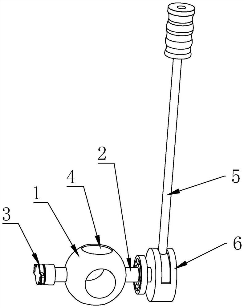
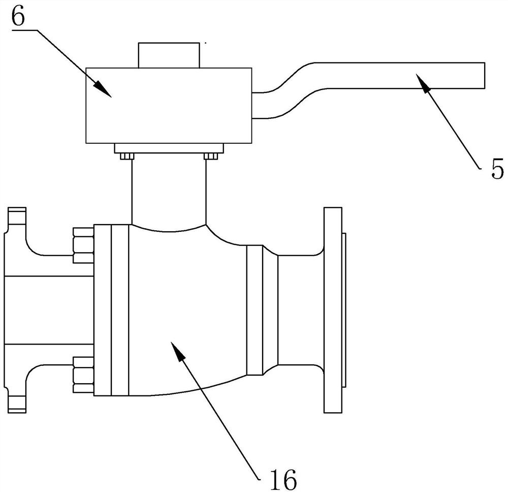
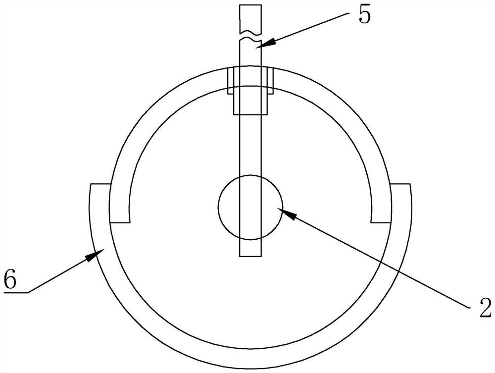
[0030] according to figure 1 As shown, the valve core is composed of a valve ball 1, a transmission rod 2, a damping gear 3 and a steering clamping device. The through hole on the valve ball 1 runs through the center of the ball. The other end of the valve is fixedly connected with the gear seat, the internal gear is installed in the gear seat, the damping gear 3 is connected with the internal gear, the through hole on the valve ball 1 and the transmission rod 2 are vertically arranged on the same horizontal plane, and the outer surface of the valve ball 1 There is a blind hole 4 on the top, and the blind hole 4 and the through hole are vertically arranged on the same horizontal plane. The inner diameter of the blind hole 4 is the same as that of the through hole, and there are two blind holes 4. , when the fluid in the valve is water or petroleum, microorganisms are likely t...


PUM


Abstract

The invention discloses a valve core, a valve using the valve core and a method thereof. The valve core includes a valve ball, a transmission rod, a damping gear and a steering clamping device. One end of the transmission rod is connected to the valve ball, and the other end is connected to the damping gear. , the valve includes a valve body, a casing and a joystick, the casing is installed on one side of the valve body, the bottom end of the joystick protrudes into the casing, and one end of the transmission rod is also placed in the casing, and is flexibly connected with the joystick. When the lever swings clockwise, the resistance is provided by the damping gear, so that the instantaneous swing range of the joystick is low, which is convenient for adjusting the flow rate. When the flow rate is directly adjusted from off to maximum, just swing the joystick counterclockwise. 0‑±90°, easy to adjust and high efficiency.

Description

technical field [0001] The present invention relates to a valve, and more particularly, to a valve core, a valve and a method using the valve core. Background technique [0002] Valves are control components in fluid delivery systems. It can be used to control the flow of various types of fluids such as air, water, steam, various corrosive media, mud, oil, liquid metal and radioactive media. [0003] At present, most industrial valves are adjusted by handwheels, because the rotation speed of the handwheels is easy to control, and it is convenient to adjust the flow rate. However, in the process of opening the flow rate from the smallest to the largest, the handwheel often needs to be turned multiple times, and the work efficiency is low. In addition, for ball valves, when the valve is closed for a long time, impurities or microorganisms in the fluid will adhere to the surface of the valve ball, and turning the valve ball again will drive the impurities or microorganisms on...

Claims


Application Information

Patent Timeline
Patent Type & Authority Patents(China)
IPC IPC(8): F16K5/06F16K5/08F16K31/60F16K35/00
CPCF16K5/0605F16K5/08F16K31/60F16K35/00
Inventor 左成林许泉彬
Owner WENZHOU ZHENHONG VALVE BALL CO LTD
Learn More