Hydraulic centrifugal fan of optimized structure

A centrifugal fan and hydraulic technology, applied to liquid fuel engines, mechanical equipment, machines/engines, etc., can solve the problems of ordinary fans with fixed structures and inability to modify them

Pending Publication Date: 2018-09-14
东莞市兴东电子有限公司
View PDF0 Cites 0 Cited by
  • Summary
  • Abstract
  • Description
  • Claims
  • Application Information

AI Technical Summary

Problems solved by technology

[0004] The purpose of the present invention is to solve the problems existing in the prior art, and to provide a structurally o

Method used


Image

  • Hydraulic centrifugal fan of optimized structure
  • Hydraulic centrifugal fan of optimized structure
  • Hydraulic centrifugal fan of optimized structure

Examples


Embodiment Construction

[0018] The specific implementation manners of the present invention will be further described in detail below in conjunction with the accompanying drawings and embodiments. The following examples are used to illustrate the present invention, but are not intended to limit the scope of the present invention.

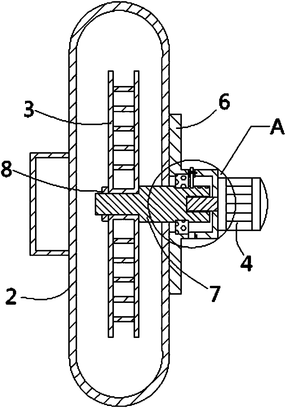
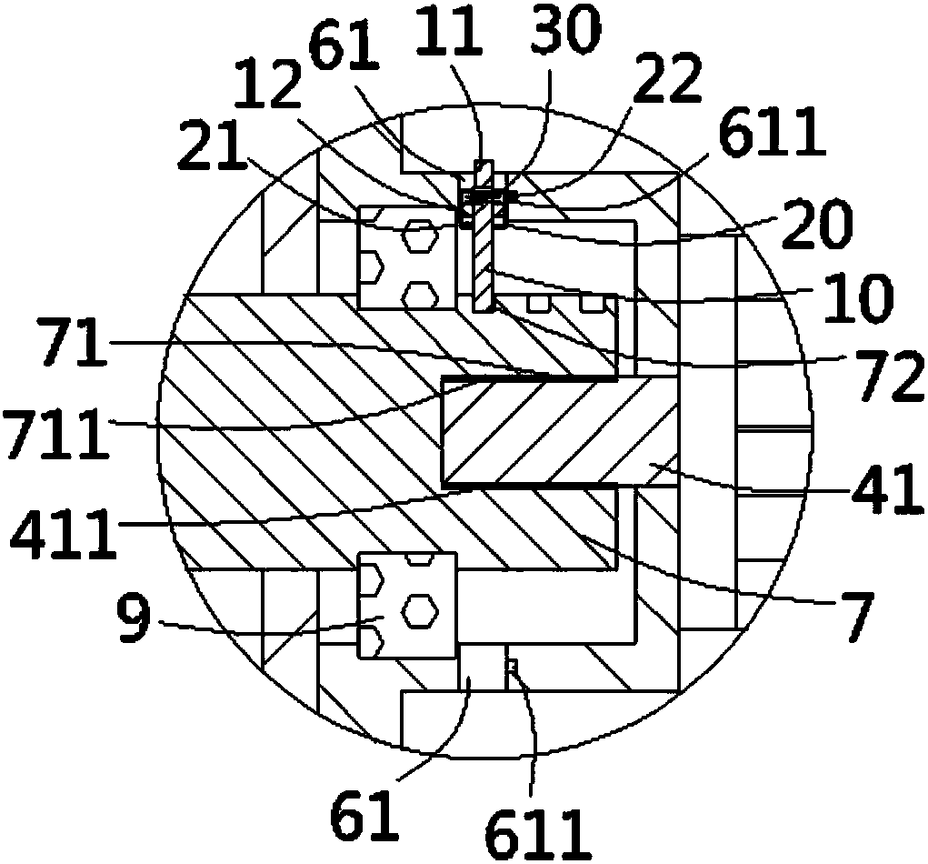
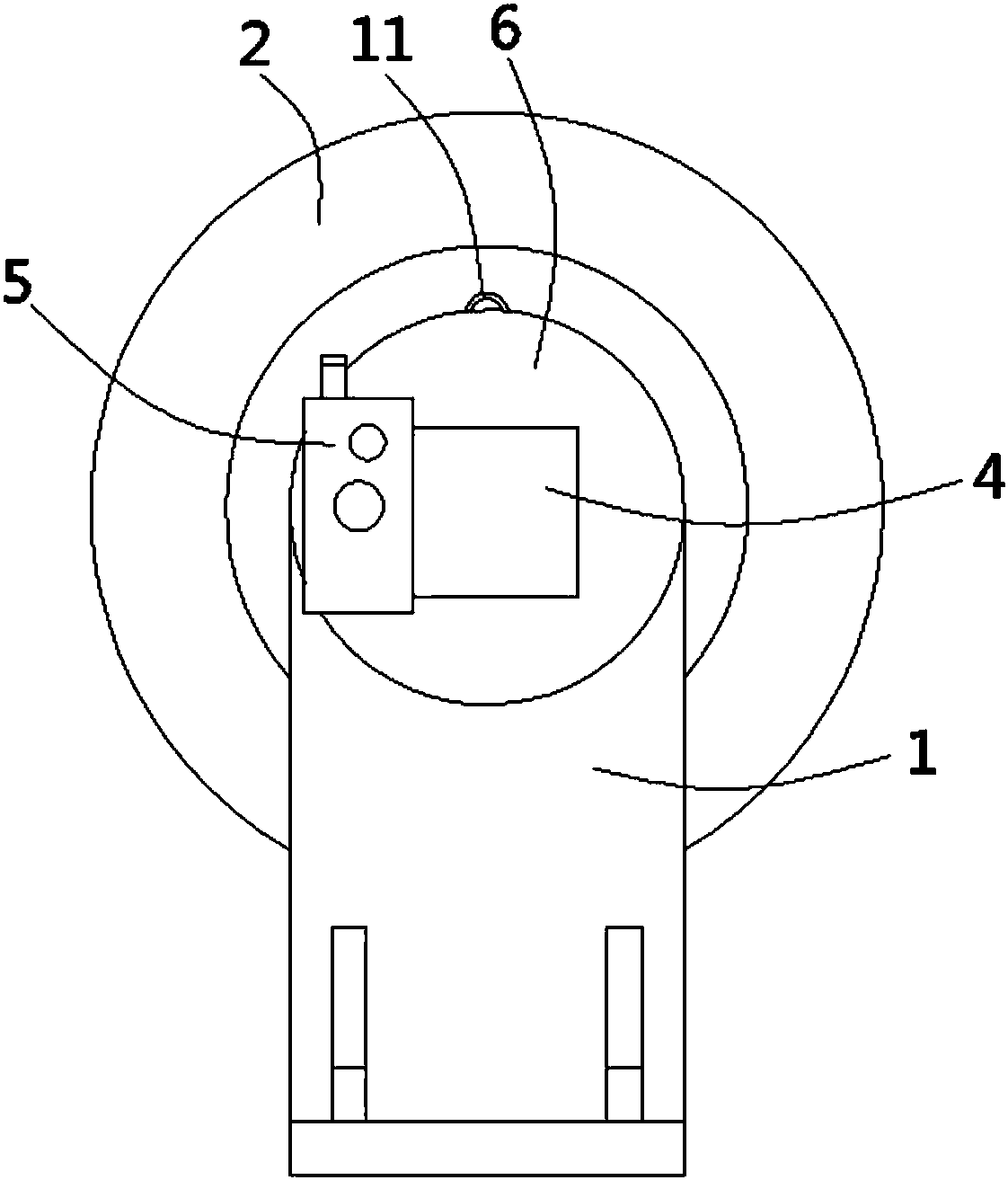
[0019] see Figure 1 to Figure 3 A structurally optimized hydraulic centrifugal fan according to the present invention includes a bracket 1, a volute 2, an impeller 3, a motor 4 and a valve block 5, and the volute 2 is fixed on the bracket 1 through a bearing base 6, The valve block 5 is connected to the motor 4, the valve block 5 is a three-way valve block, the oil inlet of the valve block 5 is connected to the external oil tank, and the oil outlet is connected to the oil inlet of the motor 4, and the motor 4 is fixed on the On the bearing base 6 and the rotating shaft 41 of the motor 4 stretches into the bearing base 6 and is fixedly connected with a transmission shaft ...


PUM


Abstract

The invention discloses a hydraulic centrifugal fan of an optimized structure. The hydraulic centrifugal fan comprises a support, a spiral casing, a vane wheel, a motor and a valve block. The spiral casing is fixed to the support through a bearing base. The motor is fixed to the bearing base, and a rotating shaft of the motor extends into the bearing base and is fixedly connected with a transmission shaft. Multiple grooves in linear arrangement are formed in the outer wall of the transmission shaft. One end of a locating rod is connected into the corresponding groove in an inserted manner. Thelocating rod is connected into a storage groove of a support seat. An annular through groove is formed in the outer side wall of the bearing base and communicates with the transmission shaft. The support seat is connected into the through groove in an inserted manner. The other end of the locating rod penetrates out of the support seat and is provided with a pull ring. One end of the pull ring penetrates out of the through groove. The part, located inside the storage groove, of the locating rod is provided with a baffle. The two ends of a compressed spring abut against the baffle and the inner wall of the storage groove correspondingly. By means of the hydraulic centrifugal fan, the problem that common fans cannot be modified due to fixed structures can be solved.

Description

Technical field: [0001] The invention relates to the technical field of centrifugal fans, in particular to a structurally optimized hydraulic centrifugal fan. Background technique: [0002] The hydraulic centrifugal fan can be used as a power fan in the air supply system or exhaust system. No viscous substances are allowed in the gas, and it can be used to transport gas in an environment where the gas temperature does not exceed 80 degrees Celsius. Most of the existing hydraulic centrifugal fans have a uniform structure and size. When encountering special circumstances, it is necessary to modify parts of the fan (such as the structure of the impeller), which becomes quite troublesome. [0003] In view of the above-mentioned defects, the designers are actively researching and innovating in order to create a hydraulic centrifugal fan with a new structure and optimized structure, so that it has more industrial value. Invention content: [0004] The purpose of the present inv...

Claims


Application Information

Patent Timeline
IPC IPC(8): F04D17/16F04D25/04F04D29/054F04D29/059F04D29/62
CPCF04D17/16F04D25/04F04D29/054F04D29/059F04D29/626
Inventor 方林秀
Owner 东莞市兴东电子有限公司
Why Eureka
Try Eureka