
Worm gear transmission mechanism and internal mixer thereof

A transmission mechanism, worm gear technology, applied in the direction of gear transmission, transmission, transmission parts, etc., can solve the problems of broken teeth, high cost, inconvenient replacement and disassembly, etc., to increase the contact area and contact stiffness, reduce teeth The effect of surface wear and easy replacement and operation

Pending Publication Date: 2018-09-14
三门县金帆橡塑机械厂
View PDF0 Cites 0 Cited by
  • Summary
  • Abstract
  • Description
  • Claims
  • Application Information

AI Technical Summary

Problems solved by technology

However, due to the small number of meshing teeth between the worm wheel and the worm, under the action of high load intensity, the meshing teeth of the worm and the worm wheel are under a large force, and the tooth surface is easy to wear, resulting in tooth chipping and broken teeth, and the service life is short.
At the same time, when the tooth surface of the worm gear is worn out, it is inconvenient to replace and disassemble, and the cost is relatively high

Method used


Image

  • Worm gear transmission mechanism and internal mixer thereof
  • Worm gear transmission mechanism and internal mixer thereof
  • Worm gear transmission mechanism and internal mixer thereof

Examples


Embodiment 1

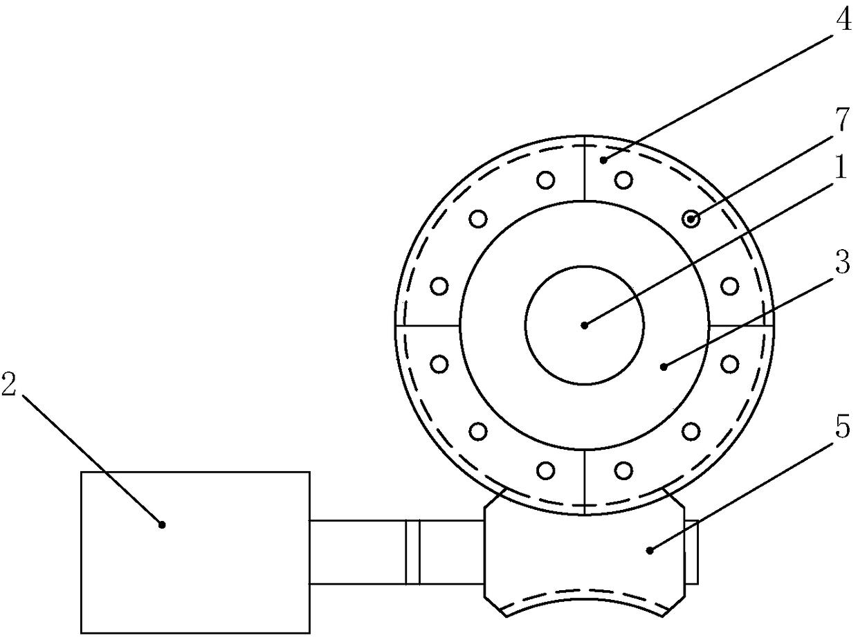
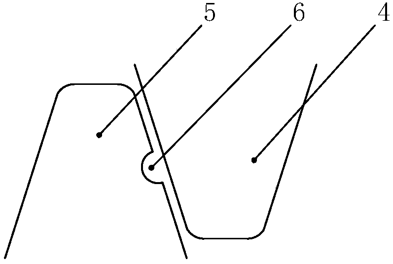
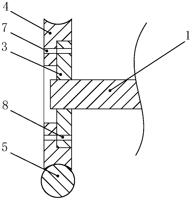
[0027] A worm and gear transmission mechanism, including a rotating shaft 1 and a driving motor 2, the rotating shaft 1 is sheathed with a worm gear, characterized in that: the worm gear includes a gear seat 3 sleeved on the rotating shaft 1 and a gear seat 3 sleeved on the rotating shaft 1 The toothed ring 4 on the top, the tooth seat 3 and the toothed ring 4 are detachably connected, the axial tooth profile of the toothed ring 4 is an inwardly concave arc-shaped structure, and the toothed ring 4 is meshed with a toroidal worm 5. One end of the toroidal worm 5 is connected to the output shaft of the driving motor 2 through a coupling. When the tooth surface on the toothed ring 4 is severely worn, only the toothed ring 4 needs to be replaced, which effectively saves the replacement cost of the worm gear. At the same time, when the toothed ring 4 is meshed with the toroidal worm 5, since the axial tooth profile of the toothed ring 4 is arc-shaped, the contact area between the t...

Embodiment 2

[0034] The structure of this embodiment is basically the same as that of Embodiment 1, the difference being that the toothed ring 4 in this embodiment is an annular structure divided into two or more. When the tooth surface of the worm gear is severely worn, it is only necessary to replace the equally worn geared ring 4 , which can further reduce the replacement cost of the worm gear.

Embodiment 3

[0036] The structure of this embodiment is basically the same as that of Embodiment 1, the difference being that the toothed ring 4 of this embodiment is an annular structure divided into two or more, and the inner wall of the toothed ring 4 is provided with an axial positioning groove. The structure is: the middle part of the inner wall surface of the toothed ring 4 is radially outwardly recessed to form a slot 11, the cross section of the slot 11 is a U-shaped structure, and the toothed ring 4 is clamped on the tooth seat 3 through the slot 11 On the outer edge of the slot 11 , the through holes 7 are symmetrically arranged on both side walls of the slot 11 .

[0037] At the same time, in order to prevent the gap between the toothed ring 4 and the tooth seat 3 in the axial direction and affect the transmission stability of the worm wheel and the toroidal worm 5, the distance between the two side walls of the locking groove 11 is less than or equal to that of the tooth seat 3...


PUM


Abstract

The invention belongs to the technical field of internal mixers, and particularly relates to a worm gear transmission mechanism and an internal mixer thereof. A rotating shaft and a driving motor areincluded, the rotating shaft is sleeved with a worm wheel, the worm wheel comprises a tooth holder arranged on the rotating shaft in a sleeving manner and a toothed ring arranged on the tooth holder in a sleeving manner, the tooth holder is detachably connected with the toothed ring, the axial tooth profile of the toothed ring is of an inwards-sinking arc-shaped structure, the toothed ring is connected with a ring surface worm in a meshed manner, and one end of the ring surface worm is in transmission connection with an output shaft of the driving motor. According to the worm gear transmissionmechanism and the internal mixer, the tooth holder is detachably connected with the toothed ring,, after tooth faces of the toothed ring are seriously abraded, only the toothed ring needs to the replaced, the replacement operation is convenient, and the worm wheel replacing cost can be effectively saved; and the axial tooth profile of the toothed ring is arc-shaped, the contact area and the contact stiffness of the toothed ring and meshing teeth of the ring surface worm can be strengthened, and abrasion of the meshed tooth faces is reduced.

Description

Technical field: [0001] The invention belongs to the technical field of internal mixers, in particular to a worm gear transmission mechanism and an internal mixer thereof. Background technique: [0002] As one of the important components of the internal mixer, the transmission mechanism is mainly used to transmit power to make the rotor rotate against the working resistance to complete the rubber mixing operation. During the working process, in order to complete the rubber mixing operation, the internal mixer needs to consume a lot of power, and the speed of the rotor is not high, so the transmission mechanism needs to carry a relatively large load intensity. The general structure of the transmission mechanism of the existing internal mixer is as follows: one end of the rotor is provided with a rotating shaft, the rotating shaft is sleeved with a worm gear, the worm gear meshes with the worm, and the drive motor drives the worm to rotate through the reducer, thereby driving ...

Claims


Application Information

Patent Timeline
Patent Type & Authority Applications(China)
IPC IPC(8): F16H1/16F16H55/22F16H55/12F16H55/10F16H57/04
CPCF16H1/16F16H55/10F16H55/12F16H55/22F16H57/0464F16H57/0498
Inventor 孙轶
Owner 三门县金帆橡塑机械厂
Learn More