Two-phase flow interface parameter measuring method

A technology of interface parameters and measurement methods, applied in the direction of measuring devices, instruments, etc.

Active Publication Date: 2018-09-14
NUCLEAR POWER INSTITUTE OF CHINA
View PDF14 Cites 9 Cited by
  • Summary
  • Abstract
  • Description
  • Claims
  • Application Information

AI Technical Summary

Problems solved by technology

[0005] The purpose of the present invention is to provide a two-phase flow interface parameter measurement method to realize the effective measurement of the interface parameters of the two-phase flow whose flow field changes rapidly under transient conditions, and solve the problem that the traditional probe measurement method is no longer suitable for transient conditions. Measurement of Interface Parameters of Two-Phase Flow in Working Conditions

Method used


Image

  • Two-phase flow interface parameter measuring method
  • Two-phase flow interface parameter measuring method
  • Two-phase flow interface parameter measuring method

Examples


Embodiment 1

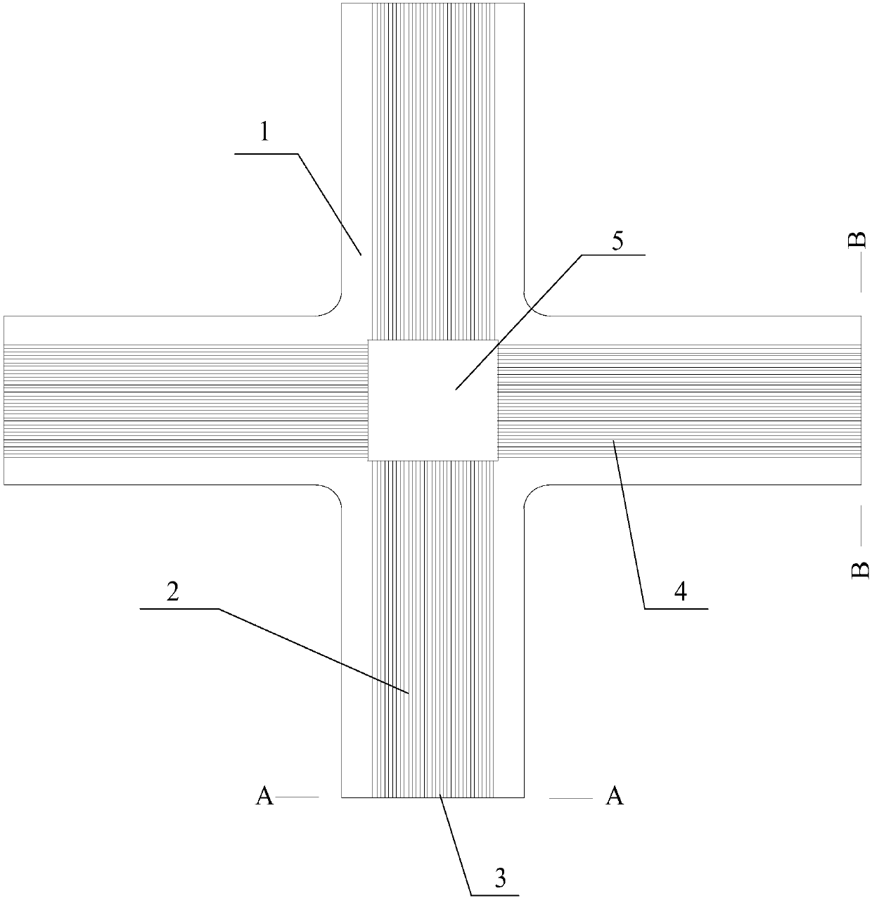
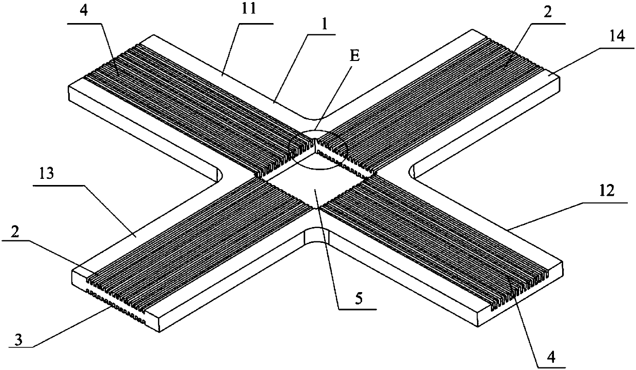
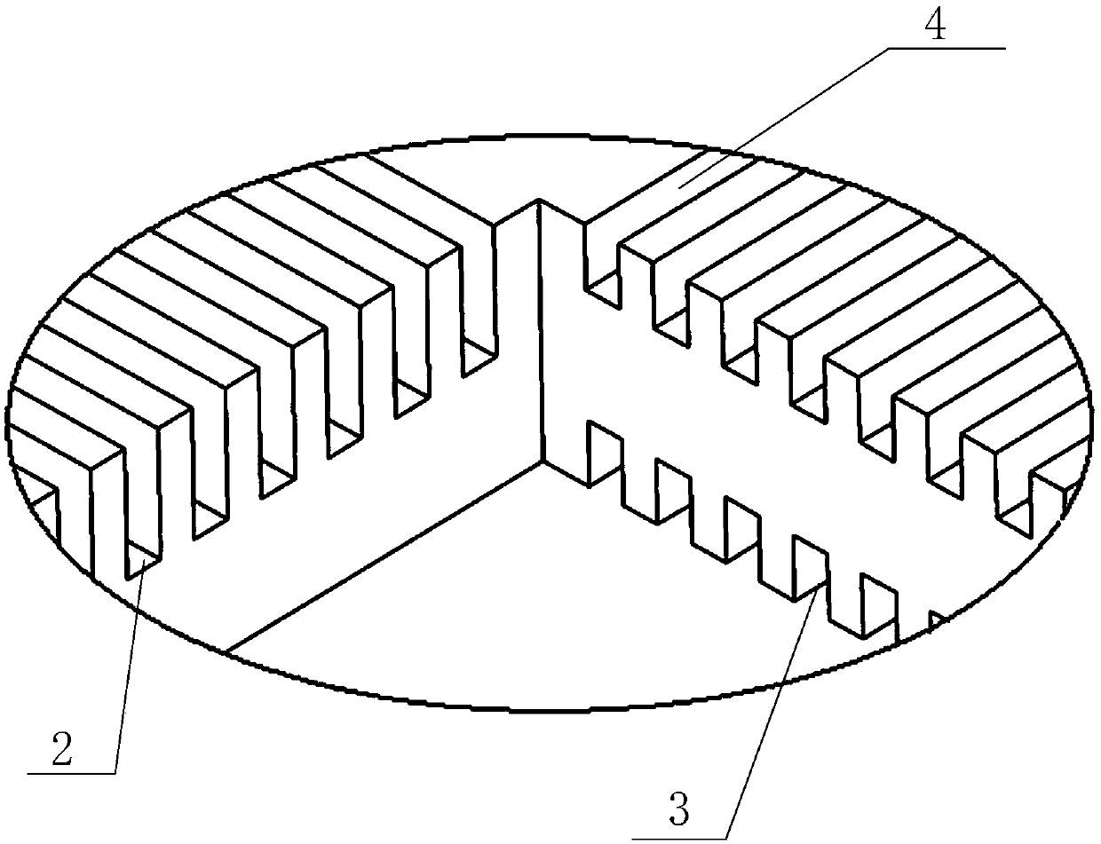
[0121] In this embodiment, a phase detector for measuring the phase distribution signal of the cross-section of the flow channel under transient working conditions is provided.

[0122] Such as Figure 1-Figure 8 As shown, the phase state detector includes a substrate 1, and the center of the substrate 1 is provided with a flow channel hole 5 penetrating the upper and lower surfaces of the substrate 1. The axial direction of the flow channel hole 5 is a vertical direction, and the flow channel hole 5 is provided with 3 There are three electrode wire layers, which are respectively the upper electrode wire layer, the middle electrode wire layer and the lower electrode wire layer, and the plane where each electrode wire layer is located is perpendicular to the central axis of the flow channel hole 5 . Each electrode wire layer includes a plurality of electrode wires arranged in parallel and located in the same plane, and the electrode wires in each electrode wire layer are evenly...

Embodiment 2

[0149] In this embodiment, a measurement system for the cross-section full-field interface parameters in two-phase flow experiments under transient conditions is provided to ensure real-time, accurate and stable measurement of cross-section full-field interface parameters under transient conditions. The in-depth study of two-phase flow under working conditions provides data support. Such as Figure 9 As shown, the two-phase flow interface parameter measurement system includes an excitation signal control unit, a phase detection device and a receiving signal processing unit, and the phase detection device is the phase detector in Embodiment 1; the middle part of the phase detector The electrode wires of the electrode wire layer are used as excitation electrode wires 6 for transmitting excitation signals in the measurement of two-phase flow interface parameters, and the electrode wires of the upper electrode wire layer and the lower electrode wire layer are used as receiving ele...


PUM


Abstract

The invention discloses a two-phase flow interface parameter measuring method adopting a two-phase flow interface parameter measuring system for measurement. The two-phase flow interface parameter measuring system comprises three layers of electrode wires used as exciting electrode wires and receiving electrode wires. The method comprises the steps as follows: S1, an exciting signal control unit generates an exciting signal and sends the exciting signal to all exciting electrode wires; S2, the exciting electrode wires receive and transfer the exciting signal to the receiving electrode wires; S3, all detection points on the receiving electrode wires acquire a current signal and send the current signal to a received signal processing unit; S4, the received signal processing unit receives thecurrent signal sent by a phase state detection device and calculates interface parameters according to the received current signal, wherein the interface parameters comprise void fraction, interfacearea concentration, bubble size and bubble speed. The whole interface parameters on sections can be measured in real time, accurately and stably under an instantaneous condition, and data support is provided for conducting deep study of two-phase flow under the instantaneous condition.

Description

technical field [0001] The invention relates to the field of two-phase flow experiments and tests, in particular to a method for measuring two-phase flow interface parameters. Background technique [0002] Gas-liquid two-phase flow is common in reactor systems. In-depth research on the characteristics and mechanism of two-phase flow has important guiding significance for thermal safety analysis of reactors, improving system operation efficiency, and proposing accident mitigation measures. Obtaining the full-field interface parameters on the cross-section of the flow channel is a prerequisite for in-depth research on two-phase flow. Important interface parameters include void fraction, interface area concentration, bubble size, and bubble velocity. [0003] So far, the most widely used measurement method is the probe. The probe can only measure the same point in the flow field at the same time. In order to obtain the distribution shape of the interface parameters on the cross...

Claims


Application Information

Patent Timeline
Patent Type & Authority Applications(China)
IPC IPC(8): G01D21/02
CPCG01D21/02
Inventor 余诗墨龚随军张君毅袁德文许爱威闫晓昝元锋
Owner NUCLEAR POWER INSTITUTE OF CHINA
Why Eureka
Try Eureka