Cam rotation type clamping device

A rotary and cam technology, applied in the mechanical field, can solve the problems of empty or unclamped, easily confused test tubes, test tube falling off, etc., to achieve the effect of guaranteed quality, novel structure, and easy assembly and disassembly

Inactive Publication Date: 2018-09-18
HUNAN DISAI BIOTECH CO LTD
View PDF0 Cites 3 Cited by
  • Summary
  • Abstract
  • Description
  • Claims
  • Application Information

AI Technical Summary

Problems solved by technology

[0002] In the sampling and sampling monitoring of test tubes, it is essential to take and place the test tubes. In the prior art, manual sampling is usually used, which is not only inefficient, but also easy to confuse the test tubes. When mechanical sampling is used, it is easy to cause the test tubes Empty or unclamped test tubes fall off during the sampling process, so a cam-rotating clamping device is provided to solve the above problems

Method used


Image

  • Cam rotation type clamping device
  • Cam rotation type clamping device

Examples


Embodiment Construction

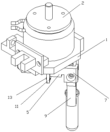
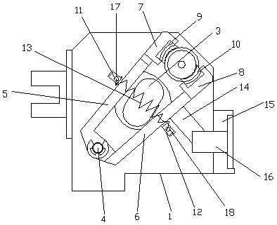
[0012] The present invention will be further described below in combination with specific embodiments. Wherein, the accompanying drawings are only for illustrative purposes, showing only schematic diagrams, rather than physical drawings, and should not be construed as limitations on this patent; in order to better illustrate the embodiments of the present invention, some parts of the accompanying drawings will be omitted, Enlargement or reduction does not represent the size of the actual product; for those skilled in the art, it is understandable that certain known structures and their descriptions in the drawings may be omitted.

[0013] like figure 1 , figure 2 As shown, a cam 3 rotary clamping device includes a base plate 1, a motor 2, a cam 3, a pin shaft 4, a left swing arm 5, a right swing arm 6, a left clamping block 7, a right clamping block 8, a left Clamping plate 9, right clamping plate 10, left connection block 11, right connection block 12, spring 13, light bl...


PUM


Abstract

The invention relates to a cam rotation type clamping device which comprises a bottom plate; the bottom plate is provided with a motor; an output shaft of the motor is connected with a cam; a left swing arm and a right swing arm are arranged on the left side and the right side of the cam respectively; the other end of the left swing arm is provided with a left clamping block; the other end of theright swing arm is provided with a right clamping block; and a left connection block and a right connection block are welded to the side surfaces of the left swing arm and the right swing arm respectively and are connected with each other through a spring. The cam rotation type clamping device provided by the invention avoids blank fetching of a test tube or test tube falling in the sampling process caused by non clamping and is novel in structure, simple to operate and convenient in assembly and disassembly.

Description

technical field [0001] The invention relates to the mechanical field, in particular to a cam-rotating clamping device. Background technique [0002] In the sampling and sampling monitoring of test tubes, it is essential to take and place the test tubes. In the prior art, manual sampling is usually used, which is not only inefficient, but also easy to confuse the test tubes. When mechanical sampling is used, it is easy to cause the test tubes Empty or unclamped test tubes will fall off during the sampling process. Therefore, a cam-rotating clamping device is provided to solve the above problems. Contents of the invention [0003] The present invention is achieved through the following technical solutions: [0004] A cam rotating clamping device, including a bottom plate, a motor, a cam, a pin shaft, a left swing arm, a right swing arm, a left clamping block, a right clamping block, a left clamping plate, a right clamping plate, and a left connecting block , right connecti...

Claims


Application Information

Patent Timeline
Patent Type & Authority Applications(China)
IPC IPC(8): B01L9/06
CPCB01L9/06
Inventor 王加强谢文锋赵营超
Owner HUNAN DISAI BIOTECH CO LTD
Why Eureka
Try Eureka