Punching device

A punching device and the technology on the other side, applied in the field of mechanical processing, can solve the problems of increasing the manpower burden of operators, inaccurate punching positioning, and affecting the punching effect, so as to reduce the manpower burden, avoid scrapping, and have high practicability Effect

Inactive Publication Date: 2018-09-18
ANHUI ANLAN MOLD
View PDF6 Cites 7 Cited by
  • Summary
  • Abstract
  • Description
  • Claims
  • Application Information

AI Technical Summary

Problems solved by technology

[0002] Punching equipment is required for punching processing and installation holes for sheet metal processing, but the existing punching equipment still has many shortcomings in actual use, such as low punching efficiency, and operators need to carry out punching operations on the pu

Method used


Image

  • Punching device
  • Punching device
  • Punching device

Examples


Embodiment Construction

[0021] The following will clearly and completely describe the technical solutions in the embodiments of the present invention with reference to the accompanying drawings in the embodiments of the present invention. Obviously, the described embodiments are only some, not all, embodiments of the present invention. Based on the embodiments of the present invention, all other embodiments obtained by persons of ordinary skill in the art without making creative efforts belong to the protection scope of the present invention.

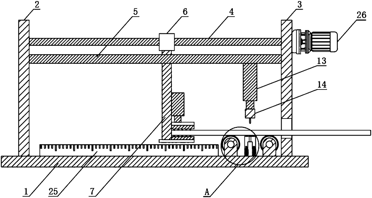
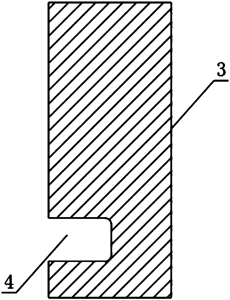
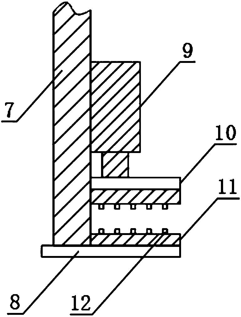
[0022] The present invention provides such as Figure 1-4 The shown punching device includes a bottom plate 1, a left side plate 2 is provided on one side of the top of the bottom plate 1 and a right side plate 3 is provided on the other side of the top, and a card slot 4 is provided on the right side plate 3 A screw 5 and a limiting plate 6 are arranged between the left side plate 2 and the right side plate 3, the outer side of the screw 5 is screwed with a m...


PUM


Abstract

The invention discloses a punching device. The punching device comprises a bottom plate, wherein a left side plate is arranged at one side of the top of the bottom plate and a right side plate is arranged at the other side of the top; a clamping groove is formed in the right side plate; a screw rod and a limit plate are arranged between the left side plate and the right side plate; a moving blockis connected to the outer side of the screw rod through a thread; a straight rod is arranged at the bottom of the moving block; a lower clamping plate is arranged at the bottom of the straight rod anda first cylinder is arranged on the side surface; an upper clamping plate is arranged at the bottom end of the first cylinder; an elastic gasket is arranged at the top of the lower clamping plate andthe bottom of the upper clamping plate separately; an elastic bar is arranged on each elastic gasket; and a second cylinder is fixedly arranged at the bottom of the screw rod. According to the punching device disclosed by the invention, the labor burden of operating personnel is effectively reduced; and meanwhile, the clamping groove is driven to rotate through a lead screw motor, so that the moving distance of a plate can be effectively controlled, the accuracy of punching location is ensured, the case of scrap of the plate is avoided, and the punching efficiency is effectively increased. The punching device is high in practicability.

Description

technical field [0001] The invention relates to the technical field of machining, in particular to a punching device. Background technique [0002] Punching equipment is required for punching processing and installation holes for sheet metal processing, but the existing punching equipment still has many shortcomings in actual use, such as low punching efficiency, and operators need to carry out punching operations on the punched parts during the punching process. This movement will increase the manpower burden of the operator. At the same time, due to the adjustment by manpower, it will easily lead to inaccurate punching positioning, affect the punching effect, and may cause the scrapping of the plate. [0003] Therefore, it is necessary to invent a punching device to solve the above problems. Contents of the invention [0004] The object of the present invention is to provide a punching device to solve the problems raised in the background art above. [0005] In order t...

Claims


Application Information

Patent Timeline
IPC IPC(8): B21D28/26B21D43/00B26F1/02B26D7/00B26D7/02
CPCB21D28/26B21D43/003B26D7/00B26D7/02B26D2007/0012B26F1/02
Inventor 王玉宝詹金珠洪家驹周勇董琪军
Owner ANHUI ANLAN MOLD
Why Eureka
Try Eureka