Shell tubular secondary spray condenser for cooling tower

A shell-and-tube cooling tower technology, applied in the field of cooling towers, can solve problems such as large floor area and overall volume, limited cooling efficiency of condensers, and inability to break through, so as to improve cooling effect, improve evaporative cooling efficiency, and wind strong cold effect

Pending Publication Date: 2018-09-18
HUNAN YUANHENG TECH CO LTD
View PDF0 Cites 0 Cited by
  • Summary
  • Abstract
  • Description
  • Claims
  • Application Information

AI Technical Summary

Problems solved by technology

[0002] Existing condensers for cooling towers such as figure 1 As shown, the condenser coil adopts a straight pipe structure, and the two ends are connected with elbows to form a circuitous and curved structure. The external cooling water is used to spray down on the upper surface of the condenser from the upper end to perform evaporative cooling. Due to structural limitations and cooling Due to the limitation of the method, the cooling efficiency of this condenser is limited and cannot be broken through. If the cooling efficiency is to be improved, the condenser is required to be made larger, so that the larger the cooling tower body, the higher the cost, the floor area and the overall The volume is also bigger

Method used


Image

  • Shell tubular secondary spray condenser for cooling tower
  • Shell tubular secondary spray condenser for cooling tower
  • Shell tubular secondary spray condenser for cooling tower

Examples


Embodiment Construction

[0027] In order to enable those skilled in the art to better understand the technical solutions of the present invention, the present invention will be described in detail below with reference to the accompanying drawings. The description in this section is only exemplary and explanatory, and should not have any limiting effect on the protection scope of the present invention. .

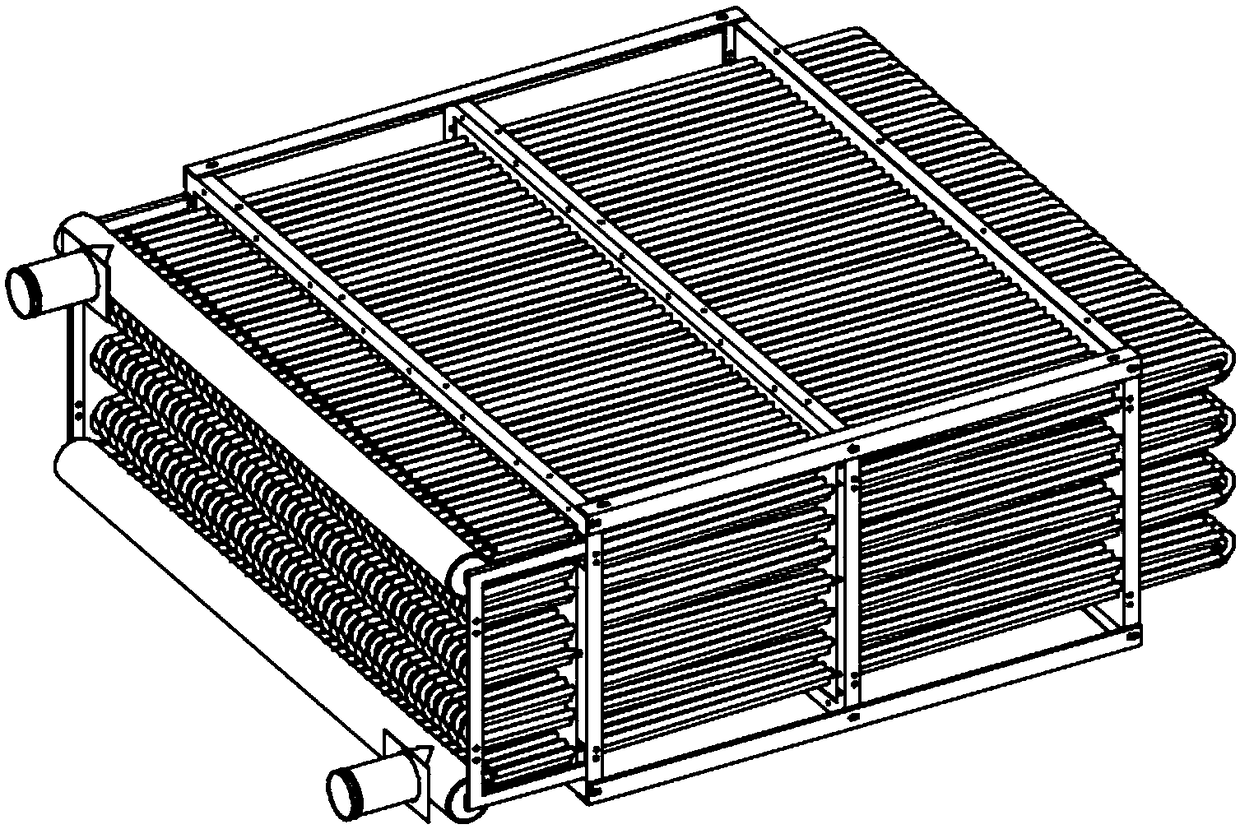
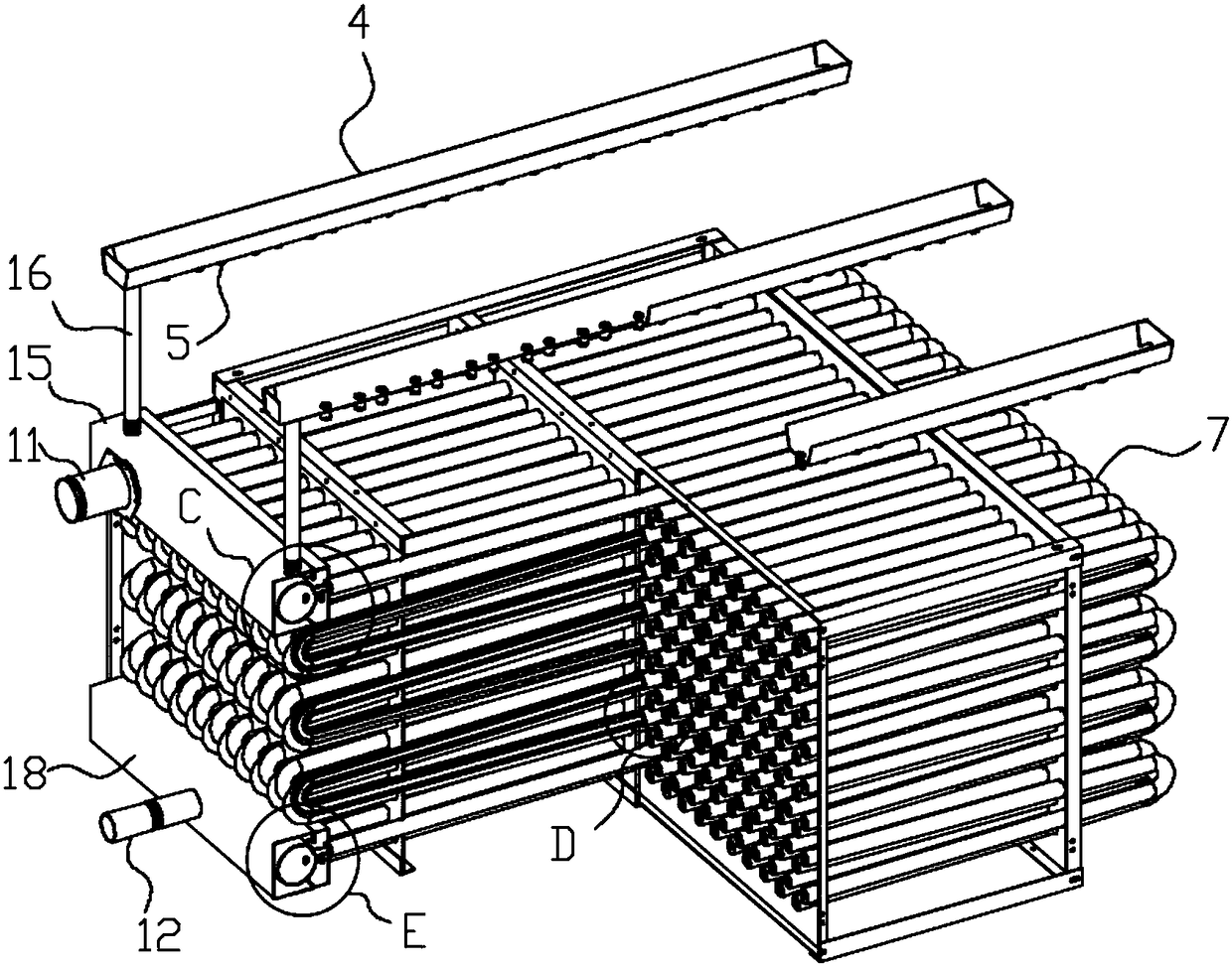
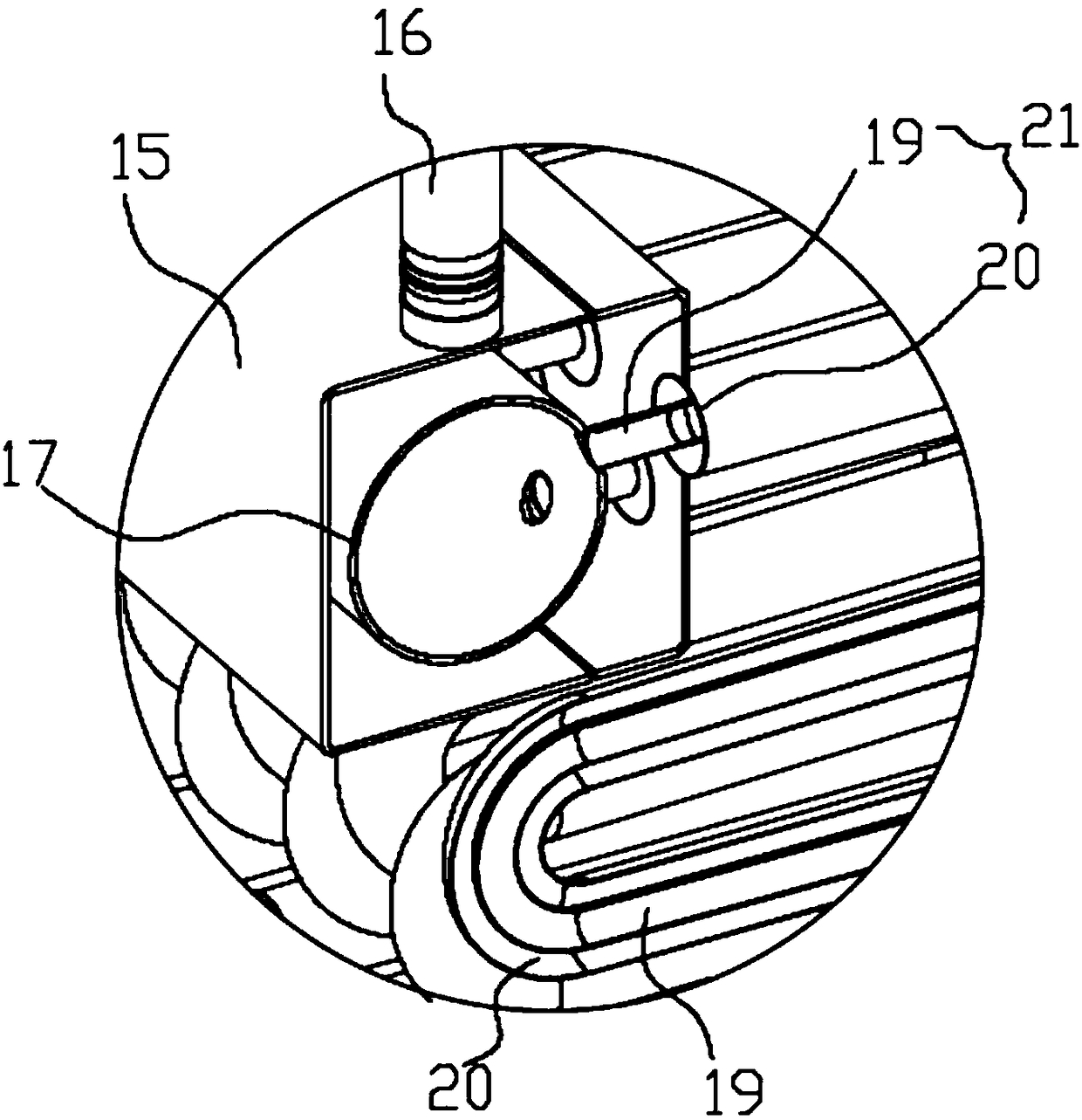
[0028] Such as Figure 2-Figure 10 As shown, the specific structure of the present invention is: a shell-and-tube secondary spray condenser for cooling towers, which includes rows of condensing coils 21, and the condensing coils 21 are double-layer pipes with a sandwich cavity. , Including the outer tube 20 of the outer layer and the inner tube 19 of the inner layer; the upper port of the outer tube 20 is connected to the upper water collecting cavity 15; the upper port of the inner tube 19 is connected to the upper collecting cavity 17; The upper collecting cavity 17 is arranged in the upper collectin...


PUM


Abstract

The invention discloses a shell tubular secondary spray condenser for a cooling tower. The shell tubular secondary spray condenser comprises condensing coils which are distributed in rows. The condensing coils comprise inner coil bodies and outer coil bodies. Upper ports of the outer coil bodies communicate with an upper water collecting cavity, and upper ports of the inner coil bodies communicatewith an upper flow collecting cavity. The upper flow collecting cavity is formed in the upper water collecting cavity. Lower ports of the outer coil bodies communicate with a lower water collecting cavity, and lower ports of the inner coil bodies communicate with a lower flow collecting cavity. The lower flow collecting cavity is formed in the lower water collecting cavity. The upper flow collecting cavity communicates with a fluid inlet pipe, and the lower flow collecting cavity communicates with a fluid outlet pipe. A branch pipe is arranged at the side edge of the lower water collecting cavity, and a water guiding pipe is arranged on the upper water collecting cavity. The upper end of the water guiding pipe is connected with a water collecting tank, and secondary spray heads are distributed on the bottom face of the water collecting tank. The water collecting tank is horizontally arranged above the condensing coils. According to the shell tubular secondary spray condenser, the heat-dissipating area is larger, full-contact-type water cooling and indirect-evaporation-type cooling can be achieved, the cooling efficiency of the condenser is improved greatly, and the efficient cooling purpose is achieved.

Description

Technical field [0001] The invention belongs to the technical field of cooling towers, and specifically is a shell and tube type secondary spray condenser for cooling towers. Background technique [0002] The existing condenser for cooling towers such as figure 1 As shown, the condenser coil adopts a straight pipe structure with elbows connected at both ends to form a circuitous and curved structure. The external cooling water is sprayed from the upper end down on the upper surface of the condenser to perform evaporative cooling. Due to structural limitations and cooling The limitation of the method leads to the limited cooling efficiency of this kind of condenser, which cannot be broken. If the cooling efficiency is to be improved, the condenser is required to be made larger, so that the larger the cooling tower body, the higher the cost, the floor space and the overall The volume is also larger. Summary of the invention [0003] The purpose of the present invention is to solve ...

Claims


Application Information

Patent Timeline
Patent Type & Authority Applications(China)
IPC IPC(8): F28C1/14F28D3/02
CPCF28C1/14F28D3/02
Inventor 邹浩傅立新戴聪蔺城光
Owner HUNAN YUANHENG TECH CO LTD
Why Eureka
Try Eureka