Direct-flow scavenging engine cylinder liner with variable scavenging phase, direct-flow scavenging engine cylinder liner component with variable scavenging phase and direct-flow scavenging engine with variable scavenging phase

A technology for engine cylinders and cylinder liners, which is applied to engine components, combustion engines, machines/engines, etc., can solve adjustment problems, achieve the effects of expanding the adjustment range, avoiding jamming, and strengthening sealing

Pending Publication Date: 2018-09-21
TIANJIN UNIV
View PDF5 Cites 2 Cited by
  • Summary
  • Abstract
  • Description
  • Claims
  • Application Information

AI Technical Summary

Problems solved by technology

[0004] However, in the process of realizing the present disclosure, the inventors of the present application found that the position of the scavenging port in the engine cylinder liner in the prior art is fixed on the cylinder liner, so the scavenging phase is also fixed, and it is impossible to make an appropriate adjustment according to the actual working conditions. Adjustment to make the engine meet the requirements of power, economy and emission

Method used


Image

  • Direct-flow scavenging engine cylinder liner with variable scavenging phase, direct-flow scavenging engine cylinder liner component with variable scavenging phase and direct-flow scavenging engine with variable scavenging phase
  • Direct-flow scavenging engine cylinder liner with variable scavenging phase, direct-flow scavenging engine cylinder liner component with variable scavenging phase and direct-flow scavenging engine with variable scavenging phase
  • Direct-flow scavenging engine cylinder liner with variable scavenging phase, direct-flow scavenging engine cylinder liner component with variable scavenging phase and direct-flow scavenging engine with variable scavenging phase

Examples


Embodiment Construction

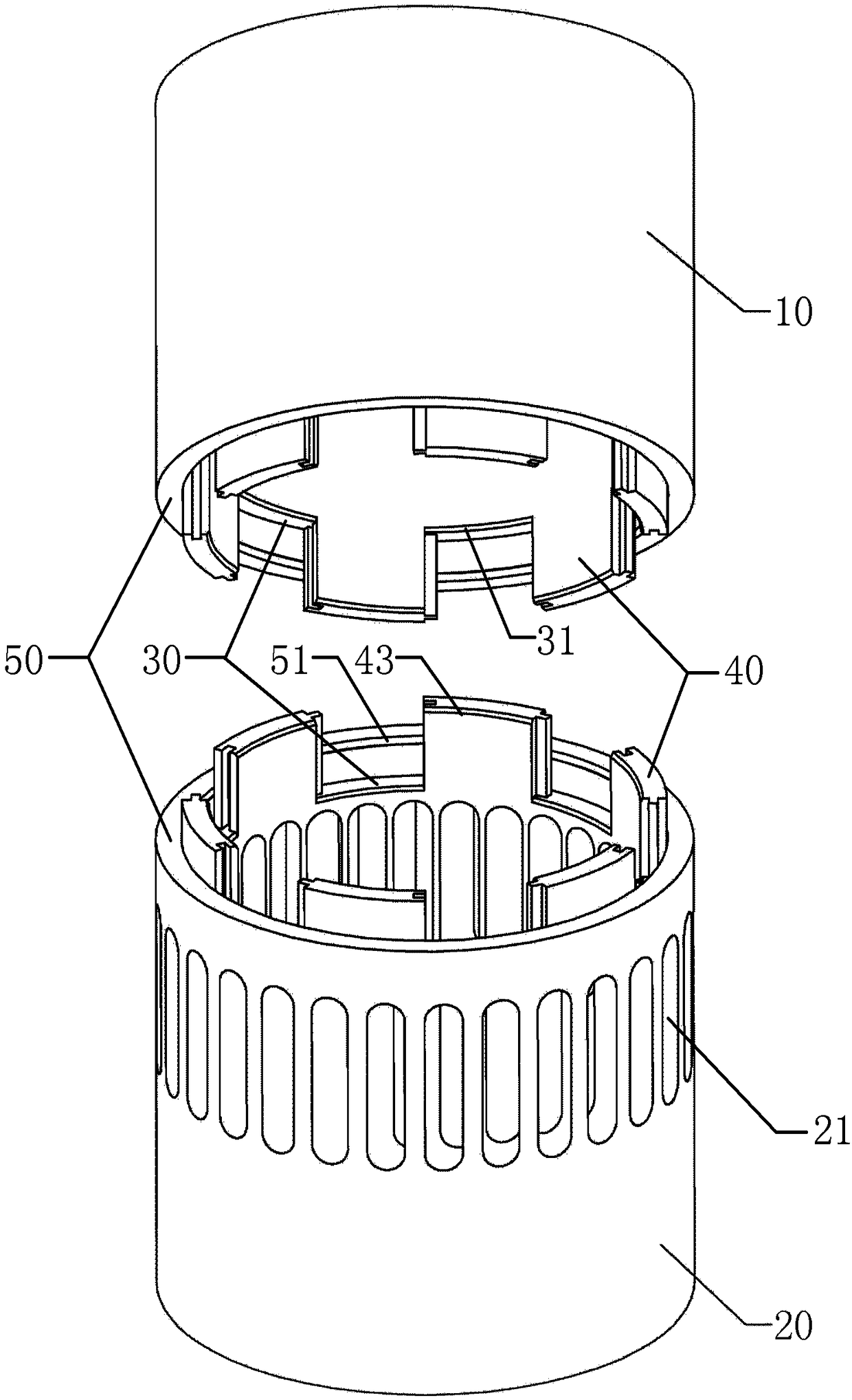
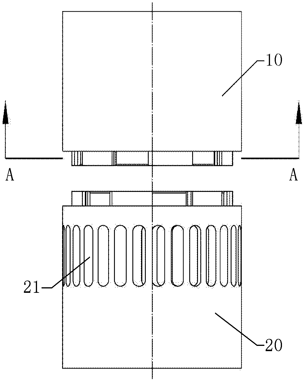
[0053]The DC scavenging engine cylinder liner, assembly and engine with variable scavenging phase provided by the embodiments of the present disclosure divide the traditional DC scavenging two-stroke engine cylinder liner into upper and lower parts near the upper end of the scavenging port. The teeth-shaped structures mesh with each other, so that the scavenging port can move up and down as a whole to change the scavenging phase, and then make appropriate adjustments according to the actual working conditions, so that the engine can meet the requirements of power, economy and emission.

[0054] In order to make the purpose, technical solutions and advantages of the present disclosure clearer, the present disclosure will be further described in detail below in conjunction with specific embodiments and with reference to the accompanying drawings.

[0055] figure 1 A schematic diagram of an exploded structure of a cylinder liner of a direct-flow scavenging engine with variable sc...


PUM


Abstract

The invention provides a direct-flow scavenging engine cylinder liner with variable scavenging phase, a direct-flow scavenging engine cylinder liner component with variable scavenging phase and a direct-flow scavenging engine with variable scavenging phase. The direct-flow scavenging engine cylinder liner with variable scavenging phase comprises: a cylinder liner upper portion, and a cylinder liner lower portion coaxial to the same and provided with a scavenging port, wherein the scavenging port moves along the axis of the cylinder liner upper portion along with the cylinder liner lower portion to change the scavenging phase, and the cylinder liner lower portion is connected with the cylinder liner upper portion in airtight manner during moving. The direct-flow scavenging engine cylinder liner with variable scavenging phase, the direct-flow scavenging engine cylinder liner component with variable scavenging phase and the direct-flow scavenging engine with variable scavenging phase havethe advantages the traditional direct-flow scavenging two-stroke engine cylinder liner is divided into upper and lower portions from the position close to the upper end of the scavenging port, toothstructures in top-bottom staggering are engaged with each other so that the whole scavenging port is moved in vertical direction to change the scavenging phase, proper adjustment can be made accordingto the actuality, and the engine gains satisfactory dynamic property, economy and emission performance.

Description

technical field [0001] The present disclosure relates to the technical field of direct-flow scavenging two-stroke engine cylinder liners, in particular to a direct-current scavenging phase engine cylinder liner, assembly and engine with variable scavenging phase. Background technique [0002] The whole process of filling the two-stroke engine with fresh air and discharging the exhaust gas is called the scavenging process. Without a good scavenging process, the engine cannot run properly. Therefore, the scavenging process is not only an indispensable part of the engine's working process, but also an extremely important link that determines the engine's dynamic performance, economy and emissions. [0003] There are a number of scavenging ports in the lower part of the cylinder liner of the DC scavenging two-stroke engine along the circumference. During the downstroke of the piston, the exhaust valve is opened for natural exhaust. As the piston continues to go down, when the u...

Claims


Application Information

Patent Timeline
Patent Type & Authority Applications(China)
IPC IPC(8): F02F1/00F02B29/00
CPCF02B29/00F02F1/004Y02T10/12
Inventor 梁兴雨杨佩剑舒歌群朱志杰刘子阳
Owner TIANJIN UNIV
Why Eureka
Try Eureka