Digital Moire phase shift interferometry method based on two-step carrier splicing method

A technology of phase-shifting interferometry and measurement method, which is applied in the field of photoelectric detection, can solve problems such as limited bandwidth, achieve the effects of improving measurement accuracy, eliminating the limitation of residual wavefront bandwidth, and expanding the measurement range

Active Publication Date: 2018-09-21
BEIJING INSTITUTE OF TECHNOLOGYGY
View PDF9 Cites 13 Cited by
  • Summary
  • Abstract
  • Description
  • Claims
  • Application Information

AI Technical Summary

Problems solved by technology

Leads to limited residual wavefront bandwidth when using digital moiré phase-shifting interferometry
The remaining wavefront bandwidth caused by the digi

Method used


Image

  • Digital Moire phase shift interferometry method based on two-step carrier splicing method
  • Digital Moire phase shift interferometry method based on two-step carrier splicing method
  • Digital Moire phase shift interferometry method based on two-step carrier splicing method

Examples


Embodiment 1

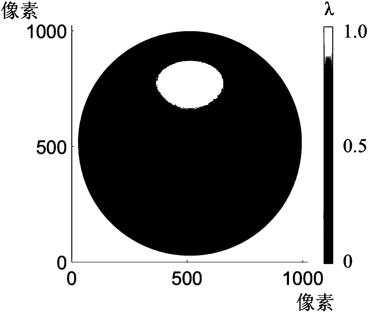
[0053] The surface shape error under rotationally symmetric wavefront is solved by digital Moiré phase-shifting interferometry method based on two-step carrier splicing method.

[0054] What is measured in this embodiment is a large residual wavefront with a PV of 84.4λ, and the distribution of the true value of the measured surface shape error is the same as figure 2 Same, PV value is 1.04λ. The maximum wavefront slope of the residual wavefront is already close to the Nyquist sampling frequency. In Example 1, the residual wavefront is used because the actual interferogram fringes are too dense to see more information with the naked eye, so the residual wavefront is used to represent , the actual calculation uses the interferogram for calculation.

[0055] The flow chart of the digital moiré phase-shifting interferometry method based on the two-step carrier splicing method disclosed in this embodiment is as follows Figure 4 As shown, the specific steps are as follows:

[...


PUM


Abstract

The invention discloses a digital Moire phase shift interferometry method based on a two-step carrier splicing method, and belongs to the photoelectric detection field. The digital Moire phase shift interferometry method based on a two-step carrier splicing method includes the steps: establishing a virtual interferometer, and obtaining an ideal system residual wavefront on an image plane of the virtual interferometer; acquiring two practical interferograms of a measured surface shape under different spatial carriers; solving the two interferograms by means of the digital Moire phase shift interferometry method respectively, and obtaining two surface shape errors with different error regions and different error regions through solution; extracting the correct areas of the two surface shapeerrors to perform splicing; and then finally obtaining the surface shape error without the error regions. Therefore, the digital Moire phase shift interferometry method based on a two-step carrier splicing method solves the problem that a digital Moire phase shift method makes solution errors when encountering the large residual wavefront, so as to expand the measurement range of the traditional solving the error in the large residual wavefront by, and then extend the measurement range of the traditional digital Moire phase shift method, eliminate the residual wavefront bandwidth limitation ofthe traditional digital Moire phase shift method and realize measurement of the measured surface shape of the large residual wavefront. The digital Moire phase shift interferometry method based on atwo-step carrier splicing method can maintain the advantages of the original digital Moire phase shift interferometry method.

Description

technical field [0001] The invention relates to a digital moiré phase-shifting interferometry method based on a two-step carrier splicing method for measuring the surface shape of an optical element by laser interferometry, and belongs to the field of photoelectric detection. Background technique [0002] Compared with the spherical surface, the aspheric surface has more surface shape freedom, and one aspheric mirror can achieve the effect of a lens group composed of multiple spherical mirrors, which can greatly reduce the size and quality of the optical system and improve the imaging quality of the system , can even reach the diffraction limit, and are more and more widely used in modern optical systems. However, because of its high-degree-of-freedom surface shape, high-precision aspheric surface shape detection has always been a major problem in the field of optical detection. [0003] At present, the commonly used aspheric surface shape detection methods are mainly divid...

Claims


Application Information

Patent Timeline
IPC IPC(8): G01B11/24
Inventor 胡摇陶鑫郝群王劭溥
Owner BEIJING INSTITUTE OF TECHNOLOGYGY
Why Eureka
Try Eureka