

Pot with temperature display function
A technology for displaying functions and pots, which is applied to household appliances, kitchen utensils, cooking utensils, etc., can solve the problems of accelerated aging of electronic components, high failure rate, and difficulty in accurately grasping temperature, and achieves the effect of simple structure.
Inactive Publication Date: 2018-09-25
梁龙飞
View PDF0 Cites 64 Cited by
- Summary
- Abstract
- Description
- Claims
- Application Information
AI Technical Summary
Problems solved by technology
[0003] In order to overcome the problem that it is difficult to accurately control the temperature during the cooking of pots, and the installation of electronic components and circuits in high-temperature environments will lead to accelerated aging of electronic components and high failure rates. The invention provides a temperature display function. Pot
Method used
View moreImage
Smart ImageViewing Examples

Examples
Embodiment Construction
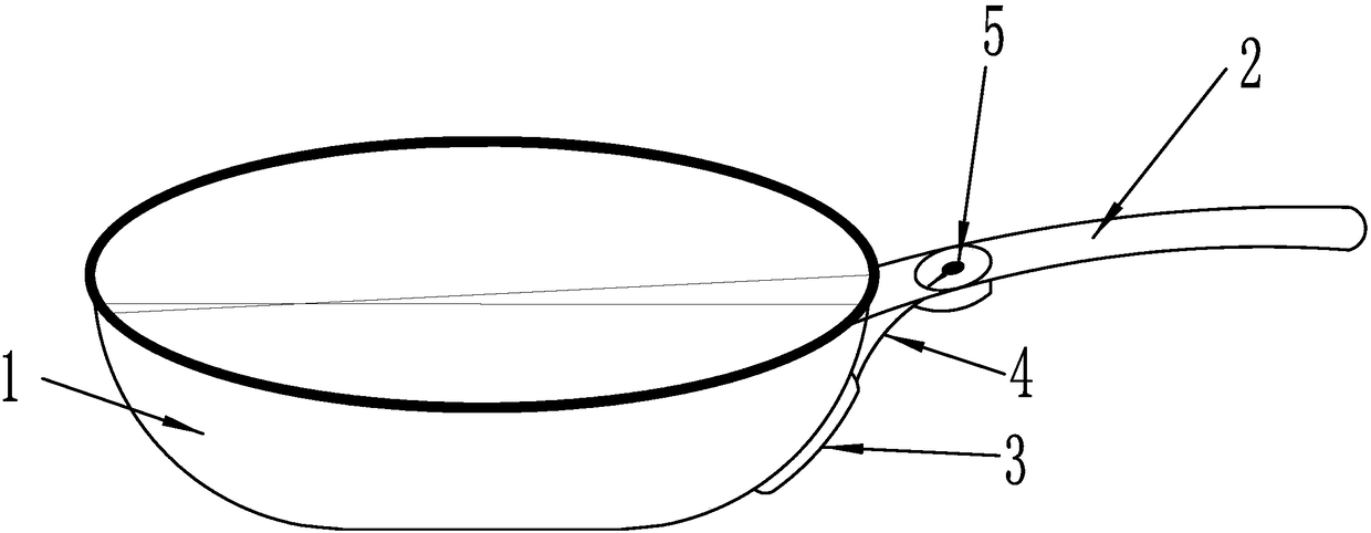
[0008] When the temperature of the pot body (1) rises, the fluid medium in the temperature sensing bulb (3) expands, and the pressure change of the temperature sensing bulb (3) is transmitted to the pressure gauge (5) on the pot handle (2) through the capillary tube (4) , the pointer of the pressure gauge (5) points out the corresponding temperature value. The displacement of the pointer of the pressure gauge (5) is related to the pressure in the temperature-sensing package (3), that is, to the temperature value of the measured pot.
Login to View More PUM
 Abstract
The invention discloses a pot with the temperature display function. A temperature sensing bulb is arranged on a pot body, and is filled with a certain quantity of fluid media; a pressure meter is arranged on a pot handle, and the temperature sensing bulb is connected with the pressure meter through a capillary tube to form a closed system; when the temperature of the pot body is changed, pressurein the temperature sensing bulb is changed, and is transferred to the pressure meter on the pot handle through the capillary tube, and a pressure-meter pointer points out corresponding temperature values. The displacement of the pot is related to the pressure in the temperature sensing bulb, namely, is related to a temperature value of a detected pot body.
Description
technical field [0001] The invention relates to a cooking utensil technology, especially capable of displaying the temperature of the cooking utensils in use. Background technique [0002] At present, in the use of cooking pots, it is difficult to accurately control the temperature. When the pot temperature is high, there will be oily smoke, and the ingredients will become mushy, and if the pot temperature is low, the ingredients will not be cooked easily. In some inventions, an electronic component circuit is added to the pot to display the temperature of the pot, but because the pot is mostly used in a high-temperature environment, the aging of the electronic component is accelerated, and the failure rate is high. Contents of the invention [0003] In order to overcome the problem that it is difficult to accurately control the temperature during the cooking of pots, and the installation of electronic components and circuits in high-temperature environments will lead to a...
Claims
Login to View More Application Information
Patent Timeline
 Patent Type & AuthorityApplications(China)
IPC IPC(8): A47J27/00A47J45/06
CPCA47J27/00A47J45/068
Inventor梁龙飞
Owner梁龙飞