Eureka AIR delivers breakthrough ideas for toughest innovation challenges, trusted by R&D personnel around the world.

Water drainage and storage concrete pavement structure and construction method

A technology for concrete pavement and drainage ditch, applied in the direction of roads, roads, pavement details, etc., can solve the problems of long construction period, poor smoothness of pavement surface, and poor durability, so as to improve the utilization rate, prevent edge damage, and improve resistance Effect of temperature load capacity

Active Publication Date: 2018-09-25
JIANGXI BOHUI ENG TECH SERVICE CO LTD
View PDF7 Cites 5 Cited by
  • Summary
  • Abstract
  • Description
  • Claims
  • Application Information

AI Technical Summary

Problems solved by technology

Although this kind of pavement can alleviate the pavement water to a certain extent and has good anti-skid performance, the flatness and durability of the pavement surface layer are poor, and the construction period is long
[0004] In summary, although the existing concrete pavement structure and construction methods have achieved good results under suitable working conditions, there is still room for improvement in the performance of the pavement, the improvement of construction efficiency, and the improvement of drainage and storage performance. Further improvements

Method used


Image

  • Water drainage and storage concrete pavement structure and construction method
  • Water drainage and storage concrete pavement structure and construction method
  • Water drainage and storage concrete pavement structure and construction method

Examples


Embodiment Construction

[0041]The following are preferred embodiments of the present invention. It should be pointed out that for those skilled in the art, without departing from the principle of the present invention, some improvements and modifications can also be made, and these improvements and modifications are also considered as the present invention. protection scope of the invention.

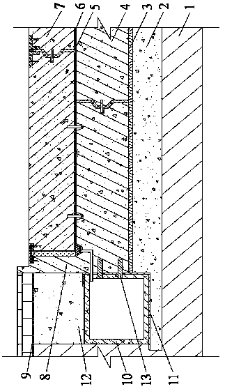
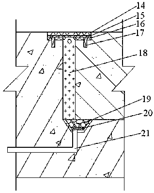
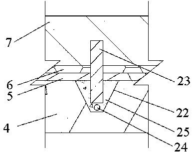
[0042] The invention provides a drainage and storage concrete pavement structure, such as Figure 1~4 As shown, the concrete pavement structure includes an embankment 1, a semi-rigid base 2, a bonded waterproof layer 3, a lower assembly plate 4 and an upper assembly plate 7 from bottom to top; the lower assembly plate 4 and the upper assembly plate 7 A flexible waterproof layer 5 and a board surface drainage board 6 are sequentially provided at the transverse joints of the bottom to top; an end plate 8 is provided on the outside of the lower assembly plate 4, and the end plate 8 and the lower assembly plate 4 a...


PUM


Abstract

The invention provides a water drainage and storage concrete pavement structure, which comprises an embankment, a semi-rigid base layer, a bonded waterproof layer, a lower assembly board and an upperassembly board in sequence from bottom to top, wherein a flexible waterproof layer and a plate drainage board are arranged at a lateral joint of the lower assembly board and the upper assembly board,end plates are arranged on the outer side of the lower assembly board, the end plates and the lower assembly board are integrally prefabricated, the top surface elevation is the same as the elevationof an outer side slow track, and prefabricated water tanks are arranged at the lower side of the slow track and the outer side of the lower assembly board. According to the invention, the upper assembly board is arranged between the end plates on the outer side of the lower assembly board, and the flexible waterproof layer and the plate drainage board are arranged at the lateral joint of the upperassembly board and the lower assembly board, so that not only is the lateral movement of the upper assembly board limited, but also the influence of temperature stress on the single-layer board can be reduced, and the interlayer movement of a water body can be achieved. The prefabricated water tank is arranged on the outer side of the lower assembly board and communicated with a built-in drain pipe, so that rainwater on a road surface can be stored and reused.

Description

technical field [0001] The invention relates to the field of road engineering, in particular to a drainage and storage concrete pavement structure and a construction method. Background technique [0002] In the construction and construction process of urban roads and highways in my country, how to effectively shorten the construction period, save project cost and road performance indicators under the premise of ensuring the quality of project construction is often the focus of engineering and academic circles. At the same time, as the road is an important collection area of ​​rainwater, how to improve the drainage performance and durability of the pavement structure has become an important factor restricting the construction of road engineering. [0003] At present, concrete pavement construction usually requires on-site reinforcement and concrete pouring. Although the construction technology and structure have the characteristics of simple on-site construction technology an...

Claims


Application Information

Patent Timeline
IPC IPC(8): E01C11/22E01C11/02
CPCE01C11/02E01C11/225E01C11/227E01C2201/20
Inventor 韩尚宇李华王新泉
Owner JIANGXI BOHUI ENG TECH SERVICE CO LTD
Why Eureka
Eureka Blog
Learn More