

Portable apparatus component fixation structure
A technology of portable equipment and fixed structure, which is applied in the direction of supporting equipment for clocks, mechanically driven clocks, and time indicating mechanical devices, etc. It can solve the problems of increased thickness of clocks and watches, damage to the appearance of clocks and watches, etc., to ensure positioning accuracy and easy installation Effect
- Summary
- Abstract
- Description
- Claims
- Application Information
AI Technical Summary
Problems solved by technology
Method used
Image

Examples
no. 1 Embodiment approach
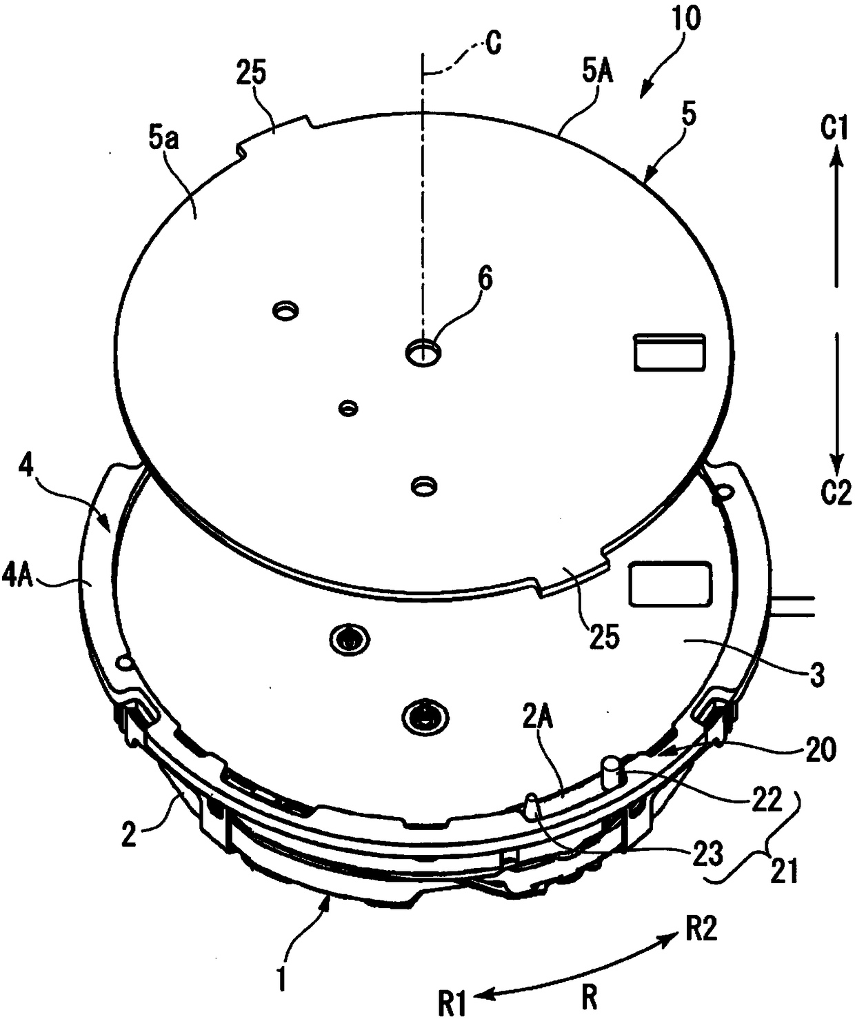
[0061] figure 1 It is an exploded perspective view showing the timepiece 10 of the first embodiment.
[0062] Such as figure 1 As shown, the timepiece 10 has a movement 1 and a display panel 5 . The movement 1 includes a bottom plate 2, a solar cell 3, a housing 4, and a pointer shaft (not shown). The display panel 5 is a second member, and the chassis 2 is a first member.
[0063] C is the central axis of the timepiece 10 . One of the directions along the central axis C is referred to as a first axial direction C1, and the direction opposite to the first axial direction C1 is referred to as a second axial direction C2. The central axis C passes through the center of the movement 1 (the bottom plate 2 , the solar cell 3 , the frame 4 and the pointer axis) and the display panel 5 . The direction around the center axis C is referred to as a circumferential direction R. One of the circumferential directions R is referred to as a first circumferential direction R1, and the dir...
no. 2 Embodiment approach
[0098] Figure 4 It is a top view showing the fixing structure 40 of the second embodiment. Figure 5 It is a side view showing the fixing structure 40 of the second embodiment.
[0099] Such as Figure 4 , Figure 5 As shown, in the fixing structure 40, the restricting part 25 of the first embodiment is replaced with the restricting part 42, and other structures are the same as the fixing structure 20 of the first embodiment.
[0100] In the restricting part 42, the second side 25b of the restricting part 25 of the first embodiment is replaced with the second side 42a, and other configurations are the same as those of the restricting part 25 of the first embodiment.
[0101]The second side 42 a of the restricting portion 42 is an inclined side facing the inclined surface 23 a of the second pin 23 . The second side 42 a of the restricting portion 42 is formed in an inclined shape along the inclined surface 23 a of the second pin 23 . Therefore, the entire surface of the s...
no. 3 Embodiment approach
[0103] Image 6 It is a top view showing the fixing structure 50 of the third embodiment. Figure 7 It is a side view showing the fixing structure 50 of the third embodiment.
[0104] Such as Image 6 , Figure 7 As shown, in the fixing structure 50, the second pin 23 of the first embodiment is replaced with the second pin 52, and other structures are the same as those of the fixing structure 20 of the first embodiment.
[0105] The second pin 52 is formed such that its diameter gradually increases from the base plate 2 toward the display plate 5 (first axial direction C1 ). That is, the inclined surface 52 a of the second pin 52 is formed so as to gradually move away from the axis 53 from the bottom plate 2 toward the first axis direction C1 . The inclined surface 52 a forms the outer peripheral surface of the second pin 52 .
[0106] The second pin 52 is attached to the base plate 2 from the side of the display panel 5 as indicated by arrow F3. As a means for attaching...
PUM
 Abstract
Description
Claims
Application Information