Buried type water purifying device

A technology for water purification and purification devices, applied in chemical instruments and methods, filtration separation, separation methods, etc., can solve the problems affecting water quality filtration, inconvenience, and inability to understand the water purification function and water quality of water purification devices in time. Easy to replace and clean, easy to transport and install

Inactive Publication Date: 2018-09-28
白仕啟
View PDF0 Cites 0 Cited by
  • Summary
  • Abstract
  • Description
  • Claims
  • Application Information

AI Technical Summary

Problems solved by technology

[0002] The water purification device is a water purification device that flocculates and separates impurities in sewage through the counter ion effect of the flocculant. It has a flocculation tank that contacts the sewage and the flocculant and electrolyzes the sewage before or after the flocculation tank. However, with the development of science and technology, people now need water purification devices that are more convenient for installation and water quality testing; the existing water purification devices have certain disadvantages in use. First of all, the existing water purification devices cannot It is more convenient for transportation and installation. It needs to be installed and transported by specific tools. At the same time, it is necessary to make a specific water purification device in advance. Secondly, it is not possible to sample the internal water quality in a timely manner. When sampling the water quality, it needs to enter the inside of the purification device. The sampling belt brings certain inconvenience, and cannot timely understand the water purification function and water quality of the water purification device. Finally, the filter element cannot be replaced and cleaned more conveniently, and the filter element cannot be replaced in a more targeted manner. The filtration of water quality has brought a certain impact on people's use process. Therefore, we propose a buried water purification device

Method used


Image

  • Buried type water purifying device
  • Buried type water purifying device
  • Buried type water purifying device

Examples


Embodiment Construction

[0017] In order to make the technical means, creative features, goals and effects achieved by the present invention easy to understand, the present invention will be further described below in conjunction with specific embodiments.

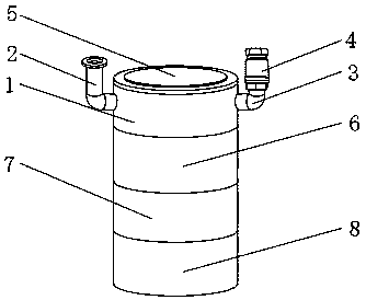
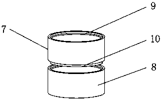
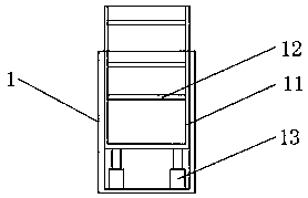
[0018] Such as Figure 1-4 As shown, a buried water purification device includes a purification device main body 1, a water inlet pipe 2 is fixedly installed on one side outer surface of the purification device main body 1, and a water outlet pipe 3 is provided on the other side outer surface of the purification device main body 1, And the outer surface of the outlet pipe 3 is provided with a ball valve 4, the center of the top outer surface of the purification device main body 1 is provided with an end cover 5, the bottom end of the purification device main body 1 is provided with a No. 1 joint body 6, and the bottom of the No. 1 joint body 6 The outer surface of the end is provided with the second segment body 7, the bottom outer surface of the ...


PUM


Abstract

The invention discloses a buried type water purifying device which comprises a purifying device body. A water inlet pipe is fixedly installed on the outer surface of one side of the purifying device body. A water outlet pipe is arranged on the outer surface of the other side of the purifying device body. A ball valve is arranged on the outer surface of the water outlet pipe. An end cap is arrangedat the center of the outer surface of the top end of the purifying device body. According to the buried type water purifying device, by arranging an annular groove, an annular pin, a sampling pipe and a filtering rack, transportation and installation can be more conveniently conducted without the aid of special tools, free installing can be conducted according to the required size, inside water can be sampled more in time, the certain inconvenience caused when people need to enter a purifying device for sampling is avoided, a filter element can be more conveniently replaced and cleaned and can be replaced with higher persistence, and better use prospects are achieved.

Description

technical field [0001] The invention relates to the field of purification devices, in particular to an underground water purification device. Background technique [0002] The water purification device is a water purification device that flocculates and separates impurities in sewage through the counter ion effect of the flocculant. It has a flocculation tank that contacts the sewage and the flocculant and electrolyzes the sewage before or after the flocculation tank. However, with the development of science and technology, people now need water purification devices that can be more conveniently installed and tested for water quality; existing water purification devices have certain disadvantages in use. First of all, existing water purification devices cannot It is more convenient for transportation and installation. It needs to be installed and transported by specific tools. At the same time, it is necessary to make a specific water purification device in advance. Secondly...

Claims


Application Information

Patent Timeline
Patent Type & Authority Applications(China)
IPC IPC(8): B01D35/30B01D35/00
CPCB01D35/00B01D35/30
Inventor 白仕啟
Owner 白仕啟
Why Eureka
Try Eureka