Punching and bending mold with angles convenient to change

A stamping, bending, and die technology, applied in forming tools, manufacturing tools, metal processing equipment, etc., can solve problems such as unfavorable production, cumbersome fixing, and cumbersome processes, saving production costs, increasing bending angles, and being easy to use. Effect

Inactive Publication Date: 2018-09-28
CHUZHOU MODERN MOLD MFG
View PDF8 Cites 2 Cited by
  • Summary
  • Abstract
  • Description
  • Claims
  • Application Information

AI Technical Summary

Problems solved by technology

[0003] There is a kind of mold that can bend the workpiece, but the bending angle is fixed, and different molds need to be replaced to bend the workpiece into different angles. However, the process of changing the mold is cumbersome, which seriously affects the work efficiency, especially the lower die. During stamping, if the lower die is unstable, it will lead to problems such as poor bending of the workpiece. Therefore, the lower die needs to be cumbersomely fixed to achieve a stable effect. Therefore, the disassembly and installation of the lower die are very cumbersome, which is not conducive to production. , and the upper die of the bending mold is generally integrally formed. If the workpiece needs to be folded at different angles, it is necessary to set the upper die with different angles. Therefore, when the upper die is damaged, the entire upper die needs to be replaced. , it will be very wasteful, so the present invention proposes a stamping and bending die that is easy to change the angle to solve the above problems

Method used


Image

  • Punching and bending mold with angles convenient to change
  • Punching and bending mold with angles convenient to change
  • Punching and bending mold with angles convenient to change

Examples


Embodiment Construction

[0023] In order to make the purpose, technical solutions and advantages of the embodiments of the present invention clearer, the technical solutions in the embodiments of the present invention will be clearly and completely described below in conjunction with the drawings in the embodiments of the present invention. Obviously, the described embodiments It is a part of embodiments of the present invention, but not all embodiments. Based on the embodiments of the present invention, all other embodiments obtained by persons of ordinary skill in the art without creative efforts fall within the protection scope of the present invention.

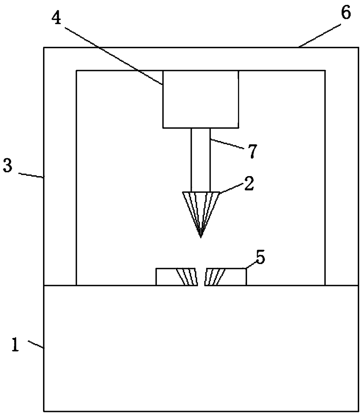
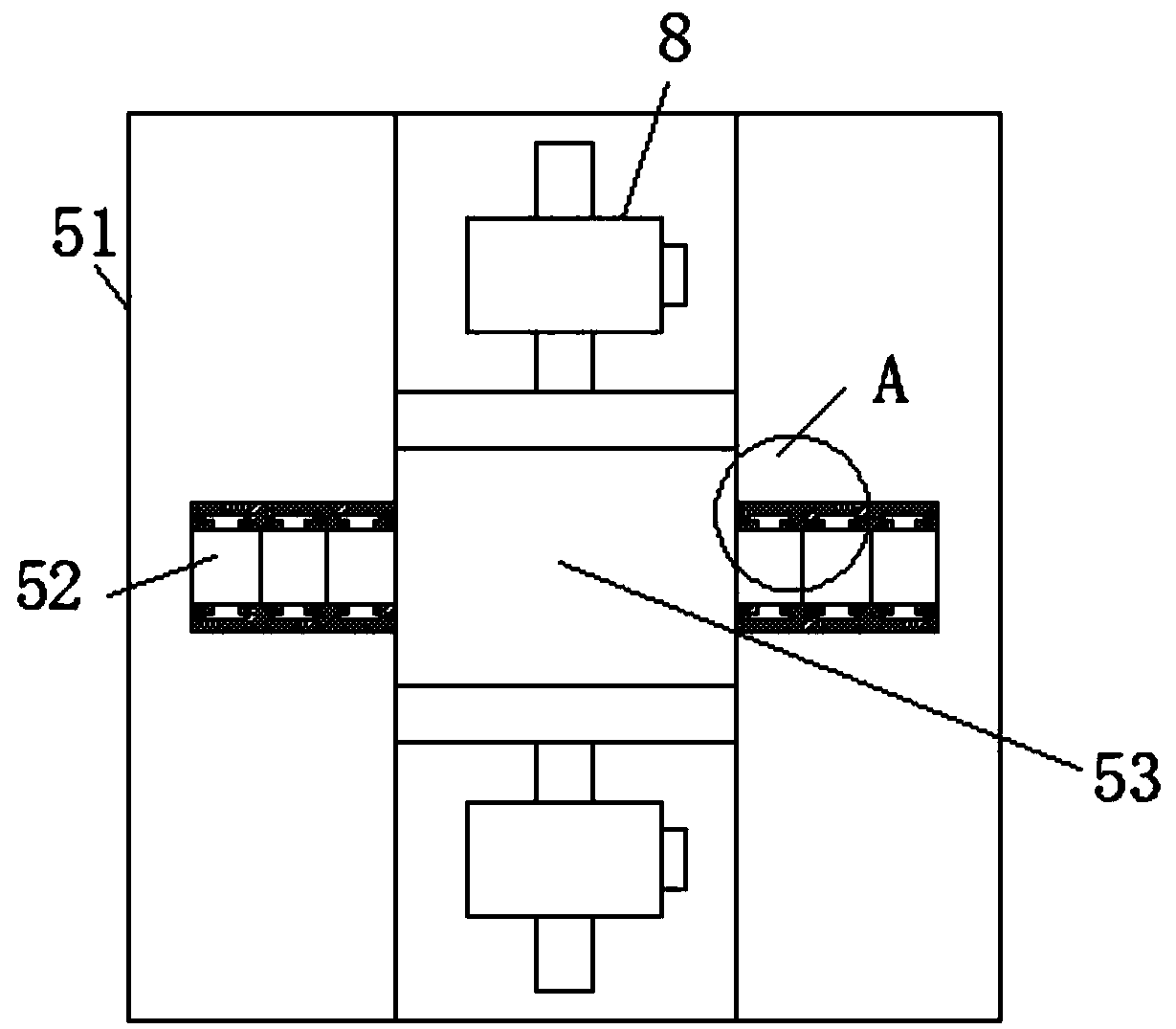
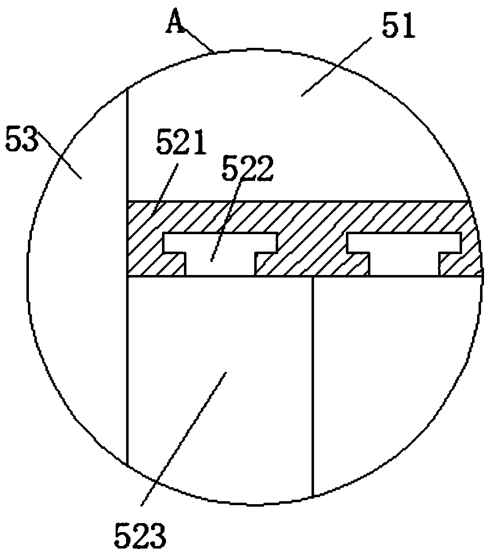
[0024] see Figure 1-3 , the present invention provides a technical solution: a stamping and bending die that is easy to change angles, including a workbench 1, an upper die 2 and a lower die 5, and a set of symmetrical support frames 3 are arranged on the workbench 1, two A connecting frame 6 is provided between the support frame 3, and a hydrau...


PUM


Abstract

The invention discloses a punching and bending mold with angles convenient to change. The mold comprises a worktable; the worktable is provided with a set of symmetric support frames; a connecting frame is arranged between the two support frames, and is provided with a hydraulic cylinder; an extension rod is arranged at one end of the hydraulic cylinder, and is connected with an upper pressing mold; the worktable is provided with a lower pressing mold; the lower pressing mold comprises a fixed base, a groove, bending grooves and a limiting device; the fixed base is arranged on the worktable; agroove is formed in middle of the fixed base; a set of symmetric limiting devices is arranged in the groove; the bending grooves are formed in the two sides of the groove; the two bending grooves aresymmetrically formed in the fixed base; the bending grooves comprise gaskets, limiting grooves and T-shaped slide plates I; limiting grooves are formed in the fixed base; multiple gaskets are arranged in the limiting grooves; the T-shaped slide plates I are arranged on the two sides of the gaskets; and the limiting grooves are provided with T-shaped chutes I cooperating with the T-shaped slide plates I. Through arrangement of the lower pressing mold, workpieces with different angles can be folded, and use is convenient.

Description

technical field [0001] The invention relates to the technical field of stamping and bending dies, in particular to a stamping and bending die which is convenient for changing angles. Background technique [0002] Stamping die is a special process equipment for processing materials (metal or non-metal) into parts (or semi-finished products) in cold stamping processing, called cold stamping die (commonly known as cold stamping die). Stamping is a pressure processing method that uses a mold installed on a press to apply pressure to the material at room temperature to cause separation or plastic deformation to obtain the required parts. [0003] There is a kind of mold that can bend the workpiece, but the bending angle is fixed, and different molds need to be replaced to bend the workpiece into different angles. However, the process of changing the mold is cumbersome, which seriously affects the work efficiency, especially the lower die. During stamping, if the lower die is uns...

Claims


Application Information

Patent Timeline
IPC IPC(8): B21D37/10
Inventor 郭勇朱金枝
Owner CHUZHOU MODERN MOLD MFG
Why Eureka
Try Eureka