
Deformable mechanical arm for high-voltage grounding rod

A ground rod and manipulator technology is applied in the field of deformable manipulators for high voltage ground rods.

Active Publication Date: 2016-10-26
STATE GRID SHANDONG ELECTRIC POWER COMPANY WEIFANG POWER SUPPLY +1
View PDF6 Cites 3 Cited by
  • Summary
  • Abstract
  • Description
  • Claims
  • Application Information

AI Technical Summary

Problems solved by technology

[0004] Since the existing high-voltage grounding rods cannot meet the needs of front-end angle changes, a high-voltage grounding rod with an elbow is mostly used now. The basic principle of the elbow of the mechanical arm is to change the angle by manually pulling the elbow, thereby To achieve the expected target function, use the spring and pull piece hanging on the reset support to realize the reset function
The outer sheath and the reset support are two different parts of the robotic arm, each with its own function. It is a bit clumsy in appearance, and the weight is also increased due to the total weight of each part, which is very inconvenient to operate.

Method used


Image

  • Deformable mechanical arm for high-voltage grounding rod
  • Deformable mechanical arm for high-voltage grounding rod
  • Deformable mechanical arm for high-voltage grounding rod

Examples


Embodiment Construction

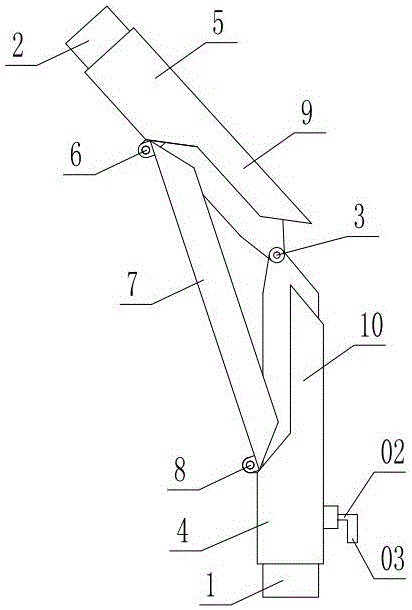
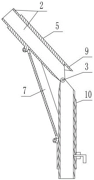
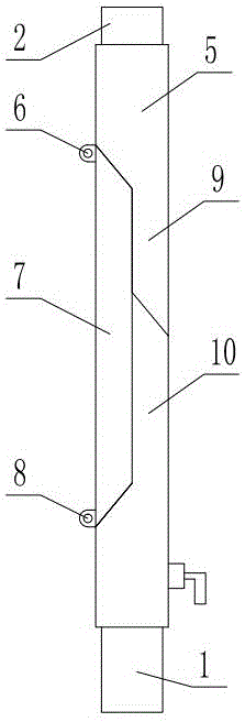
[0020] As shown in the figure, the deformable mechanical arm for high-voltage grounding rods includes a longitudinal tube 1 and a swing tube 2. The upper end of the longitudinal tube is hinged with the lower end of the swing tube through a horizontal inner hinge shaft 3, and the lower tube 4 slides up and down outside the vertical tube. , the outer fixed sleeve of the swing tube is equipped with an upper tube 5, the inner side of the lower end of the upper tube is hinged to a support arm 7 through a horizontal upper hinge shaft, the lower end of the support arm is hinged with the corresponding side of the upper end of the lower tube through a horizontal lower hinge shaft 8, and the lower end of the upper tube An upper extension plate 9 extending downward along the axial direction of the swing tube is fixed on the outer side of the swing, and a lower extension plate 10 extending upward along the axial direction of the longitudinal tube is fixed on the outer side of the upper end ...


PUM


Abstract

The invention discloses a deformable mechanical arm for a high-voltage grounding rod, which comprises a longitudinal tube and a swing tube, and is characterized in that the upper end of the longitudinal tube is hinged with the lower end of the swing tube in a matched manner through a horizontal inner hinge shaft, a lower tube externally sleeves the longitudinal tube in an up-and-down sliding manner, the external part of the swing tube is fixedly provided with an upper tube in a sleeved manner, a swing inner side of the lower end of the upper tube is hinged with a supporting arm through a horizontal upper hinge shaft, corresponding sides of the lower end of the supporting arm and the upper end of the lower tube are hinged in a matched manner through a horizontal lower hinge shaft, a swing outer side of the lower end of the upper tube is fixedly provided with an upper extension plate which extends downward along the axial direction of the swing tube, a swing outer side of the upper end of the lower tube is fixedly provided with a lower extension plate which extends upward along the axial direction of the longitudinal tube, the supporting arm also swings to a position at which the supporting arm is parallel to the longitudinal tube when the swing tube swings to a position at which the swing tube is coaxial with the longitudinal tube, the lower end of the upper extension plate is butted with the upper end of the lower extension plate in a matched manner, and the supporting arm, the upper extension plate and the lower extension plate are arranged in a close manner. The deformable mechanical arm has the advantages that the structure is reasonable, a bending or inclining operation can be carried out conveniently, the bending angle is large, bending is performed smoothly, the peripheries can be buckled into a consistent tubular shape when the swing tube swings to a straight line state, and the operation is convenient and fast.

Description

technical field [0001] The invention relates to a deformable mechanical arm for a high-voltage ground rod. Background technique [0002] The material of the high-voltage grounding rod is die-casting aluminum alloy, the structure is a spiral compression type, there is no crack in the missing corner, the operation of the grounding rod is flexible and convenient, and the surface of the insulating rod is smooth. [0003] The main components of the high-voltage grounding rod are the wire hook wire or busbar flat mouth wire clip, the jumper short-circuit wire grounding tail wire, the terminal lug, the manifold, the grounding end wire clip or the five-proof locking chuck, the grounding steel fiber and the grounding operation rod, etc. The high-voltage grounding rod provides a reliable guarantee for the safety of high-voltage and low-voltage power transmission lines and electrical equipment power outage maintenance. The high-voltage grounding rod is generally made of imported glass ...

Claims


Application Information

Patent Timeline
IPC IPC(8): H01R4/66
Inventor 张慧峰刘文波廖承民王宝秀刘桂琴滕洪全赵明春马凤勇
Owner STATE GRID SHANDONG ELECTRIC POWER COMPANY WEIFANG POWER SUPPLY
Learn More