
Portable cutter detecting instrument for CNC milling machine

A detector and portable technology, applied in the field of portable CNC milling machine tool detector, can solve problems such as inability to effectively reduce equipment damage, inability to cooperate with control processing to improve product qualification rate, inability to detect damage to tools, etc., to improve flexibility and stability, accurately detect the quality of work, reduce the effect of damage rate

Inactive Publication Date: 2018-09-28
长沙熙迈机械制造有限公司
View PDF5 Cites 0 Cited by
  • Summary
  • Abstract
  • Description
  • Claims
  • Application Information

AI Technical Summary

Problems solved by technology

[0004] The main purpose of the present invention is to overcome the deficiencies of the prior art and provide a portable CNC milling machine tool detector to solve the problem that the track of the tool position controlled by the program does not overlap with the actual cutting edge of the tool, and it is impossible to pass With the aid of the detector, it is possible to cooperate with the control process to improve the product qualification rate. At the same time, it is impossible to comprehensively detect whether the tool is damaged during the cutting process when the tool is not cutting, and it is impossible to effectively reduce the damage rate of the equipment and further improve the cutting quality. question

Method used


Image

  • Portable cutter detecting instrument for CNC milling machine
  • Portable cutter detecting instrument for CNC milling machine
  • Portable cutter detecting instrument for CNC milling machine

Examples


Embodiment Construction

[0022] The following will clearly and completely describe the technical solutions in the embodiments of the present invention with reference to the accompanying drawings in the embodiments of the present invention. Obviously, the described embodiments are only some, not all, embodiments of the present invention. Based on the embodiments of the present invention, all other embodiments obtained by persons of ordinary skill in the art without making creative efforts belong to the protection scope of the present invention.

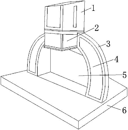
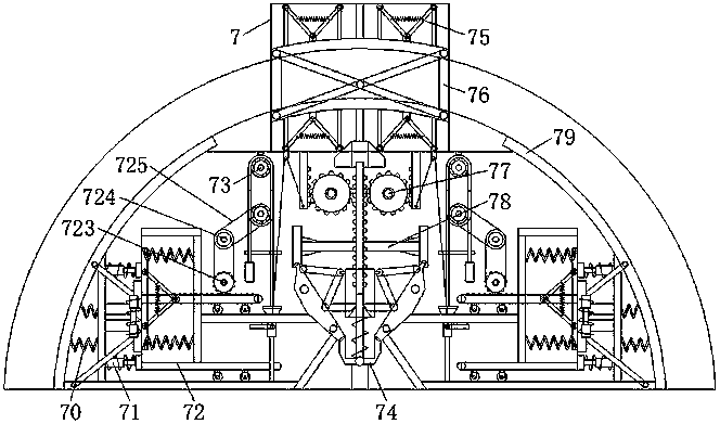
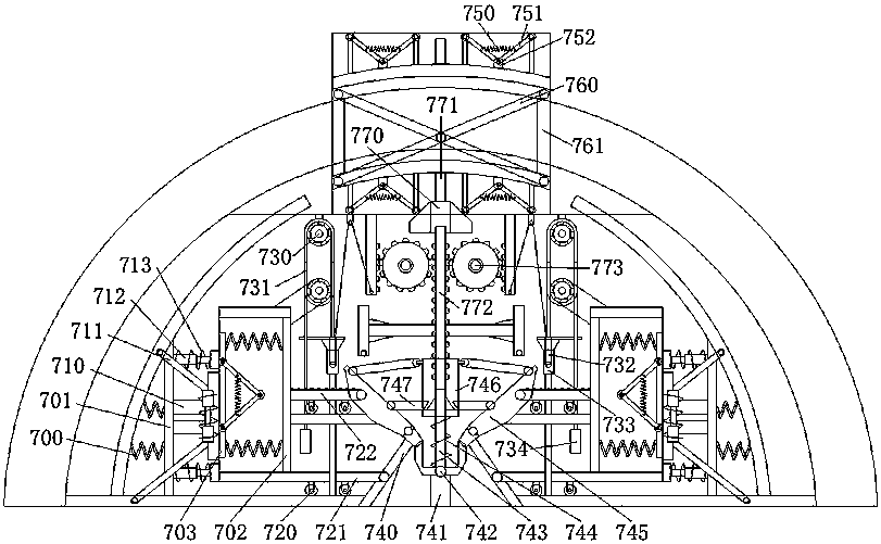
[0023] see Figure 1-3, the present invention provides a technical solution for a portable CNC milling machine tool detector: its structure includes a mounting head 1, a detector rotating head 2, a fixed cover frame 3, a detector 4, a frame position 5, a base 6, and a reinforcement device 7. The fixed cover frame 3 is perpendicular to the base 6, the groove bars of the fixed cover frame 3 and the detector 4 are connected to the track of the base 6, the fixed c...


PUM


Abstract

The invention discloses a portable cutter detecting instrument for a CNC milling machine. The portable cutter detecting instrument for the CNC milling machine structurally comprises a mounting head, adetecting instrument rotating head, a fixing covering frame, a detecting instrument body, a frame position, a base and a reinforcing device, wherein the fixing covering frame is vertical to the base;a slotted strip of the detecting instrument body is connected to a track of the base; the fixing covering frame is provided with the frame position and fits the detecting instrument body. According to the portable cutter detecting instrument for the CNC milling machine, a cutter upwards moves to drive transmission so as to realize rotating detecting, and thus whether the cutter is damaged can beuniversally detected; the cutter downwards moves to drive transmission to realize local detection, and thus a detection area can be reasonably matched, and the working quality can be accurately detected; an upward pushing transmission mechanism is subjected to X shape transmission and fixing during transmission, so that the overall transmission sensitivity and stability can be effectively improved; a first damping device, a second buffering device, a first fastening assisting mechanism and a second fastening assisting mechanism are provided, so that the damage rate of the detecting instrumentin fixing and separating can be minimized.

Description

technical field [0001] The invention relates to the field of tool testers, in particular to a portable CNC milling machine tool tester. Background technique [0002] CNC milling machine is an automatic processing equipment developed on the basis of general milling machines. The processing technology of the two is basically the same, and the structure is somewhat similar. CNC milling machines are divided into two categories: without tool magazine and with tool magazine. Among them, the CNC milling machine with a tool magazine is also called a machining center; the tool detector has high resolution and is an ideal instrument for tool inspection for non-contact surface light and transmitted light measurement on the edge of the tool and surface light measurement on the geometry of the tool head. [0003] The trajectory of the tool position controlled by the program of the prior art does not overlap with the actual cutting edge of the tool, and it is impossible to cooperate with ...

Claims


Application Information

Patent Timeline
Patent Type & Authority Applications(China)
IPC IPC(8): B23Q17/09
Inventor 曹立静郝海丽
Owner 长沙熙迈机械制造有限公司
Learn More