
Self-balanced transport vehicle

A transport vehicle and self-balancing technology, applied in the field of vehicle engineering, can solve the problems of complex structure, high cost, complex structure of the center of gravity adjustment system, etc., and achieve the effect of overcoming the risk of rollover

Inactive Publication Date: 2018-09-28
XUZHOU NORMAL UNIVERSITY
View PDF5 Cites 7 Cited by
  • Summary
  • Abstract
  • Description
  • Claims
  • Application Information

AI Technical Summary

Problems solved by technology

The structure of the center of gravity adjustment system above is complex and needs to be equipped with multiple sets of liquid systems to work normally. The structure is complex, the cost is high, and the degree of center of gravity offset is limited.

Method used


Image

  • Self-balanced transport vehicle
  • Self-balanced transport vehicle
  • Self-balanced transport vehicle

Examples


Embodiment 1

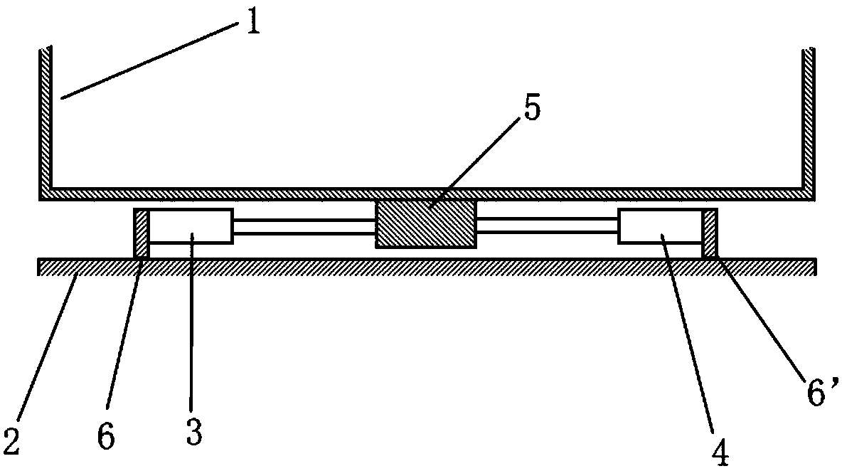
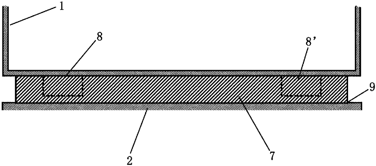
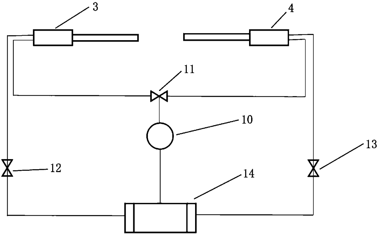
[0018] Such as Figure 1-3 As shown, a self-balancing transport vehicle includes a compartment 1, an underframe 2, a first hydraulic cylinder 3, a second hydraulic cylinder 4, a hydraulic pump 10, a three-way solenoid valve 11, a first solenoid valve 12, and a second solenoid valve 13, oil storage tank 14, pressure sensor 9 and controller. The middle part of compartment 1 is welded by channel steel along the traveling direction of the transport vehicle to form a cuboid bump 5, the two ends of the bottom of compartment 1 perpendicular to the traveling direction of the transport vehicle protrude downwards to form sliders (8, 8'), and the two ends of the chassis 2 The upper part corresponding to the slide block (8, 8') has two guide rails 7 ( figure 2 Only one of the ends is shown in ), the slider extends into (8, 8') guide rail 7 and slides a certain distance in the guide rail 7 with the left and right movement of the compartment, and the slider (8, 8') is far from the inner e...


PUM


Abstract

A self-balanced transport vehicle comprises a compartment, a bottom frame, a first hydraulic cylinder and a second hydraulic cylinder. The self-balanced transport vehicle is characterized by further comprising a hydraulic pump, a three-way solenoid valve, a first solenoid valve, a second solenoid valve, an oil storage tank, a pressure sensor and a controller. A protruding block is arranged in themiddle of the compartment in a downwards-protruding mode in the advancing direction of the transport vehicle. The two ends, perpendicular to the advancing direction of the transport vehicle, of the bottom of the compartment protrude downwards to form sliding blocks correspondingly. Two guiding rails are arranged on the upper portions, corresponding to the sliding blocks, of the two ends of the bottom frame. The sliding blocks extend into the guiding rails and slide left and right in the guiding rails along with left-right moving of the compartment. The bottoms of the first hydraulic cylinder and the second hydraulic cylinder are fixed to the bottom frame. Plungers of the hydraulic cylinders are fixed to the protruding block. According to the self-balanced transport vehicle, the guiding rails and a hydraulic mechanism are additionally arranged at the bottom of the compartment to form a gravity center adjusting system, and the gravity center of the transport vehicle shifts to a certain extent by laterally pushing the compartment when the transport vehicle turns so as to counteract centrifugal moment, so that the rollover risk when the transport vehicle turns is overcome.

Description

technical field [0001] The invention relates to vehicle engineering, in particular to a self-balancing transport vehicle. Background technique [0002] When the vehicle is running, emergency avoidance or turning speed is too fast, it is easy to cause a tipping accident due to excessive centrifugal force, causing serious losses. At present, some vehicle center of gravity adjustment systems prevent rollover by adjusting the center of gravity of the vehicle when the vehicle is turning. Patent CN200810232901 discloses a vehicle anti-rollover system, which resists part of the centrifugal moment by lowering the center of gravity of the vehicle when turning. Patent CN200910143765 discloses a car with an anti-rollover system and the anti-rollover system. When the vehicle is turning, the center of gravity is offset by tilting the car left / right to offset a part of the centrifugal force torsion moment. In addition, some adjust the center of gravity of the vehicle by loading counterw...

Claims


Application Information

Patent Timeline
Patent Type & Authority Applications(China)
IPC IPC(8): B62D37/00
CPCB62D37/00
Inventor 赵虎辰舒文淼
Owner XUZHOU NORMAL UNIVERSITY
Learn More