Clamping storage device for kits

A technology for storage devices and kits, applied in the direction of transportation and packaging, conveyor objects, etc., can solve the problems of unsuitable kits, cumbersome push and push operations, etc., and achieve the effect of convenient and automatic access

Inactive Publication Date: 2018-09-28
THE AFFILIATED HOSPITAL OF QINGDAO UNIV
View PDF9 Cites 6 Cited by
  • Summary
  • Abstract
  • Description
  • Claims
  • Application Information

AI Technical Summary

Problems solved by technology

But this invention cannot be applied to other forms of kits, and the operation of pushing and pushing at the same time is too cumbersome

Method used


Image

  • Clamping storage device for kits
  • Clamping storage device for kits
  • Clamping storage device for kits

Examples


specific Embodiment approach 1

[0029] The fixed connection mentioned in this device refers to fixing by means of welding, screw fixing, etc., and different fixing methods are used in combination with different use environments. The sliding connection described is all connected by sliding the slider in the chute .

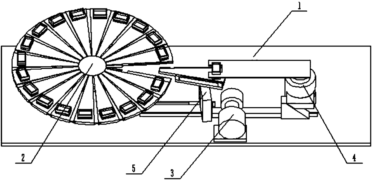
[0030] Such as Figure 1 to Figure 12As shown, a clamping storage device for a reagent box includes a base slide 1, a storage device 2, a driving device 3, a rotating clamping device 4 and a moving delivery device 5, and the storage device 2 is fixedly connected to the base slide 1 Above, the upper end of the mobile delivery device 5 is slidably connected to the storage device 2, the lower end of the mobile delivery device 5 is slidably connected to the base slide 1, the rotary clamping device 4 is fixedly connected to the base slide 1, and the left end of the rotary clamping device 4 The gap fits in the driving device 3 , the right end of the driving device 3 fits with the rotary clamping devic...

specific Embodiment approach 2

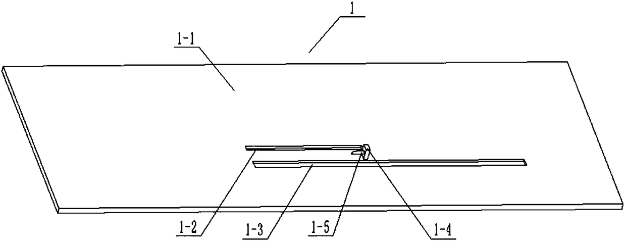
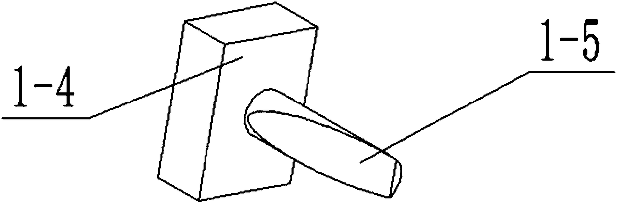
[0031] Such as Figure 1 to Figure 12 As shown, this embodiment will further describe Embodiment 1. The base slide 1 includes a base plate 1-1, a moving feeding device chute 1-2, a rack chute 1-3, a support plate 1-4 and a socket The shaft 1-5, the mobile feeder chute 1-2 and the rack chute 1-3 are all arranged on the base plate 1-1, the support plate 1-4 is fixedly connected on the base plate 1-1, and the support plate 1-4 It is arranged between the mobile delivery device chute 1-2 and the rack chute 1-3, the right end of the insertion shaft 1-5 is fixedly connected to the support plate 1-4, and the left end surface of the insertion shaft 1-5 is an inclined plane.

specific Embodiment approach 3

[0032] Such as Figure 1 to Figure 12 As shown, this embodiment will further illustrate Embodiment 2. The storage device 2 includes a rotating and fixing device 2-1, a moving plate 2-2, a reagent box moving storage box 2-3, a left chute 2-4, Right chute 2-5, large fixed groove 2-6 and small fixed groove 2-7, mobile plate 2-2 are provided with a plurality of, mutually slidingly connect between a plurality of mobile plates 2-2, all mobile plates 2-2 2 are all slidably connected on the rotating fixing device 2-1, and the upper end of each moving plate 2-2 is provided with a large fixing groove 2-6, and each large fixing groove 2-6 is provided with a small fixing groove 2-7 , each large fixed groove 2-6 is equipped with a reagent box mobile storage box 2-3 with gaps, and the left and right sides of the lower end of each mobile plate 2-2 are provided with a left chute 2-4 and a right chute 2-5, the front end and rear end of each mobile plate 2-2 are provided with a displacement sl...


PUM


Abstract

The invention relates to the field of biopharmaceuticals, in particular to a clamping storage device for kits. The clamping storage device comprises a base slide plate, a storage device, a driving device, a rotary clamping device and a movable delivery device, wherein the storage device is fixedly connected onto the base slide plate and is in sliding connection with the upper end of the movable delivery device; the lower end of the movable delivery device is glidingly connected onto the base slide plate; the rotary clamping device is fixedly connected onto the base slide plate; the left end ofthe rotary clamping device is arranged in the driving device in a clearance fit mode; the right end of the driving device is attached to the rotary clamping device, and the front end of the driving device meshes with the rotary clamping device. The clamping storage device for the kits has beneficial effects as follows: multiple kits can be stored in low-pressure, low-temperature or sterile environments or other specific environments, meanwhile, automatic storage and taking of the multiple kits are convenient, and the condition that reagents are affected in the storage and taking processes andthen experimental data are affected is avoided.

Description

technical field [0001] The invention relates to the field of biopharmaceuticals, in particular to a clipping storage device for a kit. Background technique [0002] In the fields of medicine and bioengineering, it is often necessary to store prepared reagents in kits. Combined with different experimental reagents, it is necessary to place individual kits in a specific environment such as low pressure, low temperature or aseptic, in order to avoid damage and affect the appropriate environment, specific equipment is required for the movement and storage of reagents and kits. [0003] Patent No. CN201110078305.0 discloses a device suitable for adding and ejecting plate-type reagents. The plate-type reagent plate is rotated by the motor and the transmission mechanism, and several reagent grooves are formed along the periphery in the radial direction; the reagent box placement mechanism is located next to the plate-type reagent plate, and the plate-type reagents are stacked in t...

Claims


Application Information

Patent Timeline
Patent Type & Authority Applications(China)
IPC IPC(8): B65G47/90
CPCB65G47/902
Inventor 李晓云
Owner THE AFFILIATED HOSPITAL OF QINGDAO UNIV
Why Eureka
Try Eureka