Supercharge Your Innovation With Domain-Expert AI Agents!

Coating brush device for wall

A paint brush and wall technology, applied in the direction of construction, building construction, etc., can solve the problems of speeding up adhesion, increasing the height of rolling paint, waste, etc., to achieve the effect of avoiding waste, increasing the height of paint, and speeding up the completion speed

Inactive Publication Date: 2018-09-28
余谢飞
View PDF0 Cites 0 Cited by
  • Summary
  • Abstract
  • Description
  • Claims
  • Application Information

AI Technical Summary

Problems solved by technology

[0005] Aiming at the deficiencies of the prior art, the present invention provides a paint brush device for walls, which overcomes the deficiencies of the prior art, and has a reasonable design and a compact structure. The paint can be transported into the support pipe by setting a pumping machine, and then transported to the outlet. In the material pipe, through the function of the discharge port on the outer surface of the discharge pipe, the paint can be automatically transported to the surface of the roller brush, thereby solving the problem of manual adhesion; by setting the material receiving tank, the material receiving tank can pass through the connecting pipe It is connected with the pumping machine, so that it can prevent the paint from falling and splashing on people, and it can also transport the paint to the pumping machine for reuse through the connecting pipe, thus avoiding the waste of paint. The sparse layer can prevent the paint from sticking to the inner surface of the receiving tank; by setting the blower and the air outlet, the surface can be dried after the paint, thereby speeding up its sticking; by setting the threaded sleeve, the inner telescopic rod Flexible connection with the outer telescopic rod, so that the paint height of the roller brush can be increased

Method used


Image

  • Coating brush device for wall
  • Coating brush device for wall

Examples


Embodiment Construction

[0020] In order to make the purpose, technical solutions and advantages of the embodiments of the present invention clearer, the technical solutions in the embodiments of the present invention will be clearly and completely described below in conjunction with the drawings in the embodiments of the present invention. Obviously, the described embodiments It is a part of embodiments of the present invention, but not all embodiments. Based on the embodiments of the present invention, all other embodiments obtained by persons of ordinary skill in the art without creative efforts fall within the protection scope of the present invention.

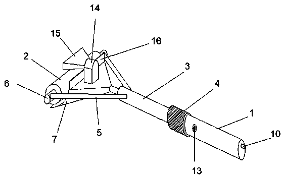
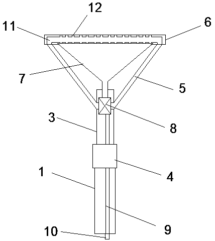
[0021] A paint brushing device for walls, comprising an outer telescopic rod 1 and a rolling brush 2, an inner telescopic rod 3 is arranged above the outer telescopic rod 1, and a threaded sleeve 4 is movably connected to the outer surface of the upper part of the outer telescopic rod 1, the The outer telescopic rod 1 is movably connected with the...


PUM


Abstract

The invention provides a coating brush device for a wall. The coating brush device comprises an outer telescopic rod and a rolling brush; the upper portion of the outer telescopic rod is movably connected with an inner telescopic rod through a threaded sleeve; a central shaft is connected to the side surface of the upper portion of the inner telescopic rod through a supporting pipe; and a materialreceiving tank is fixedly connected to the upper surface of the inner telescopic rod through a communicating pipe; and a material pumping machine is fixedly mounted on the upper portion of the interior of the inner telescopic rod, and the lower portion of the material pumping machine communicates with a feeding inlet through a feeding pipe. According to the coating brush device for the wall, thedefects in the prior art are overcome, design is reasonable, and the structure is compact; coating can be conveyed into a discharging pipe through the material pumping machine, and then the effect ofautomatic supplementing of the coating is achieved through a discharging outlet; and through the material receiving tank, the situation that the coating downwards falls to splash the human body can beprevented, and the coating can further be conveyed into the material pumping machine for repeated using through the communicating pipe.

Description

technical field [0001] The invention relates to the technical field of paint brushes, in particular to a paint brush device for walls. Background technique [0002] Decoration is a relatively popular industry. With the continuous improvement of people's living standards, the requirements for material life are also continuously improved. Therefore, in order to have a good living environment, people will decorate their office and living areas. [0003] And at present, the roller brush that people decorate is mainly made up of roller and brush bar, rolls on wall surface after sticking coating by roller and finishes, and when roller coating is higher than the metope of human body height, paint will splash and fall to people. body, which will not only cause a waste of paint, but also have an adverse effect on the personal safety of the operators; in addition, after the paint is applied to the wall, it generally waits for it to dry naturally, which not only makes the painted wall ...

Claims


Application Information

Patent Timeline
Patent Type & Authority Applications(China)
IPC IPC(8): E04F21/06
CPCE04F21/06
Inventor 梅振
Owner 余谢飞
Features
  • R&D
  • Intellectual Property
  • Life Sciences
  • Materials
  • Tech Scout
  • Unparalleled Data Quality
  • Higher Quality Content
  • 60% Fewer Hallucinations
Learn More