High-pressure and high-flow two-position four-way liquid control reversing valve

A technology of hydraulic control reversing valve and two-position four-way, which is applied in the field of hydraulic control, can solve the problems of reliability and maintainability uncertain factors, can not be applied to military projects, short closing and reversing time, etc., and the switching time can be adjusted , avoid easy stuck, smooth control effect

Active Publication Date: 2018-09-28
中国船舶重工集团公司第七0四研究所
View PDF6 Cites 2 Cited by
  • Summary
  • Abstract
  • Description
  • Claims
  • Application Information

AI Technical Summary

Problems solved by technology

However, the maximum rated flow rate of the general slide valve is below 1100L / min, the diameter is below DN50, and the opening and closing time of the valve port is long and uncontrollable.
And as the diameter of the valve port increases, the commutation impact is large, and the commutation is prone to unreliable
[0004] At present, the existing spool valve products in China generally have a diameter of 6mm to 32mm and a nominal flow rate of 60L / min to 1100L / min. The flow rate of a few foreign electro-hydraulic proportional valves with a diameter of 50mm can reach 1500L / min, but The pressure drop at the valve port is relatively large, and it needs to be customized. The reliability and maintainability have uncertain factors, which will bring greater risks to the use, and cannot be applied to important military projects.
However, when the nominal pressure is not lower than 21MPa and the pressure drop at the valve port is 0.5MPa, the flow rate can reach more than 1600L / min and the main valve opening and closing reversing time is short and adjustable hydraulic switching valves are relatively rare at home and abroad. , there are no public research reports and mature products for selection in China, so it is necessary to develop a high-pressure and large-flow two-position four-way hydraulic control valve that matches the control valve group to achieve stable control of the actuator

Method used


Image

  • High-pressure and high-flow two-position four-way liquid control reversing valve
  • High-pressure and high-flow two-position four-way liquid control reversing valve
  • High-pressure and high-flow two-position four-way liquid control reversing valve

Examples


Embodiment Construction

[0031] The technical solutions of the present invention will be described in detail below in conjunction with the accompanying drawings.

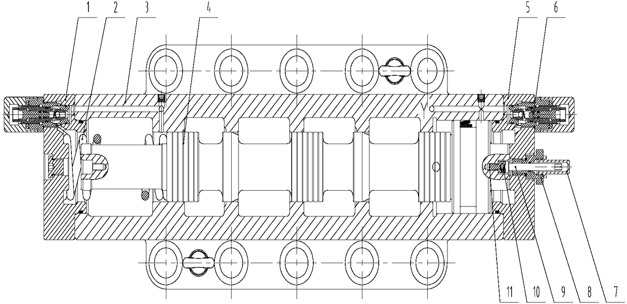
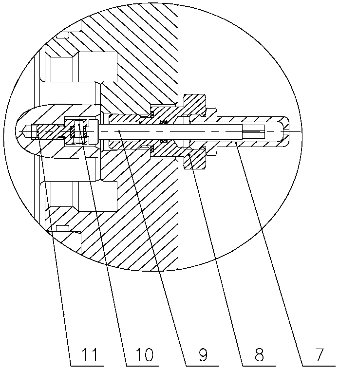
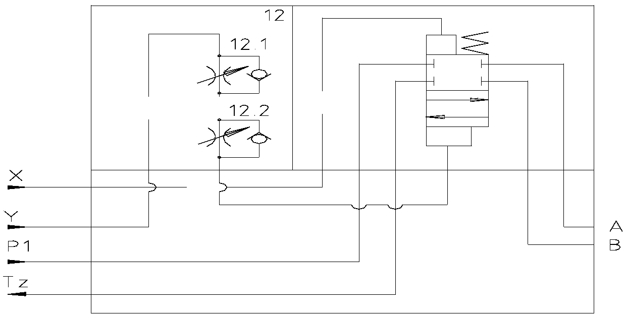
[0032] See attached figure 1 , 2 and attached image 3 , the high-pressure and large-flow two-position four-way hydraulically controlled reversing valve in this embodiment includes a left end cover 1, a return spring 2, a main valve body 3, a main valve core 4, a right end cover 5, a hydraulic buffer mechanism 6, and a protective cover 7 , Measuring sleeve 8, measuring rod 9, connecting pin 10, measuring connector 11 and speed regulating valve group 12. The speed regulating valve group 12 is composed of two speed regulating valves 12.1 and 12.2 connected in series, and is used to control the flow rate of the Y oil circuit downstream of the hydraulic control reversing valve, so as to realize the adjustment of the opening and closing switching time of the hydraulic control reversing valve valve port (The speed regulating valve group 12 can ...


PUM


Abstract

The invention relates to a high-pressure and high-flow two-position four-way liquid control reversing valve. The liquid control reversing valve comprises a left end cover, a main valve body, a main valve element and a right end cover; the main valve element is arranged in the main valve body; and the left end cover and the right end cover are arranged at the two ends of the main valve body. The high-pressure and high-flow two-position four-way liquid control reversing valve with reliable height is suitable for medium/high-pressure systems; when the pressure of a valve port is reduced by 0.5 MPa, the flow can reach above 1600 L/min, so that the valve element can realize quick switching, stable movement and no impact, and the closing and opening switching time of the valve port is adjustable. The liquid control reversing valve is particularly suitable for controlling a hydraulic motor to realize startup of a high-speed winch and stable braking control.

Description

technical field [0001] The invention relates to the field of hydraulic control, in particular to a high-pressure and large-flow two-position four-way hydraulic control reversing valve. Background technique [0002] The hydraulic control reversing valve uses the pressure of the liquid flow to push the valve core to make relative movement in the valve body to change the working position of the valve, realize the opening and closing of the oil circuit, thereby changing the direction of the liquid flow, and making the hydraulic actuator start and stop Or change the direction of motion. [0003] The structure of switch type hydraulic reversing valve mainly has two types: poppet type and slide valve type. The working principle of the poppet type is similar to that of the cartridge valve, which has good sealing performance, but the controllability of the opening and closing process of the valve port is poor. The spool valve structure is the most widely used in the hydraulic rever...

Claims


Application Information

Patent Timeline
Patent Type & Authority Applications(China)
IPC IPC(8): F15B13/02F16K11/065
CPCF15B13/02F16K11/065
Inventor 黄田忠夏魁桂文彬刘金榕王玉柱
Owner 中国船舶重工集团公司第七0四研究所
Why Eureka
Try Eureka