
Gear transmission gearbox with gear collision preventing function

A technology of gear transmission and gearbox, applied in the direction of gear transmission, transmission, transmission parts, etc., can solve the problems of transmission gear damage, gear noise, tooth beating, etc.

Inactive Publication Date: 2018-09-28
柳欢
View PDF0 Cites 2 Cited by
  • Summary
  • Abstract
  • Description
  • Claims
  • Application Information

AI Technical Summary

Problems solved by technology

[0002] At present, the existing gear transmission gearboxes often cause damage to the gearbox gears due to the user's misoperation. As far as automobile gearboxes are concerned, it is generally required to step on the clutch to the bottom during manual shifting, and then perform gear shifting operations. When the speed is basically the same, loosen the clutch and complete the gear shift. When the engine speed does not match the wheel speed, not only will there be gear noises when the user shifts gears, but it will also easily cause gear hitting. If the gear is forcibly inserted into a high-speed rotating gear, the phenomenon of tooth beating will definitely occur. In order to avoid this kind of situation, it is very necessary to design a gear transmission gearbox with the function of preventing tooth beating

Method used


Image

  • Gear transmission gearbox with gear collision preventing function
  • Gear transmission gearbox with gear collision preventing function
  • Gear transmission gearbox with gear collision preventing function

Examples


Embodiment Construction

[0051] The specific implementation manners of the present invention will be further described in detail below in conjunction with the accompanying drawings and embodiments. The following examples are used to illustrate the present invention, but are not intended to limit the scope of the present invention.

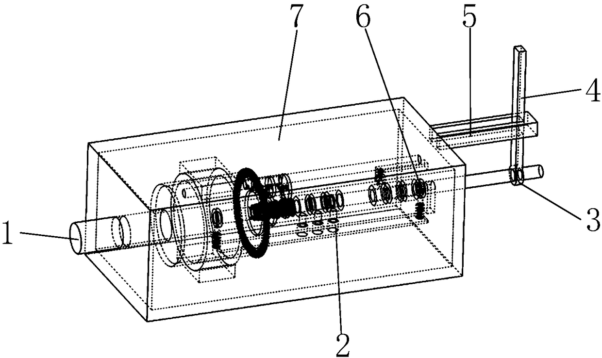
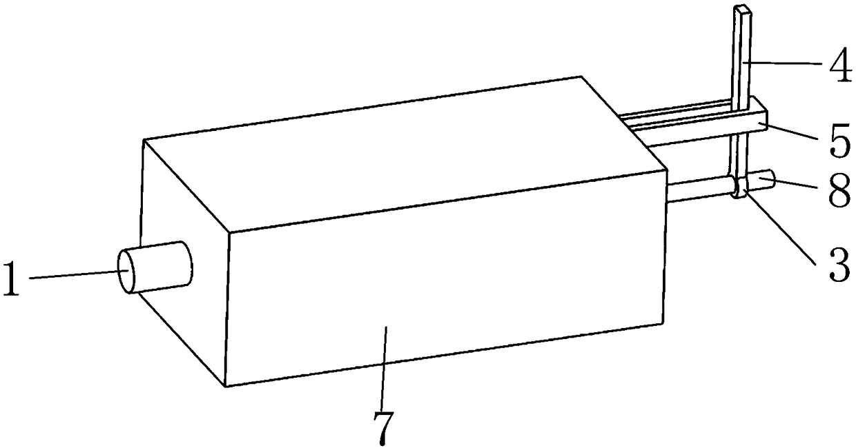
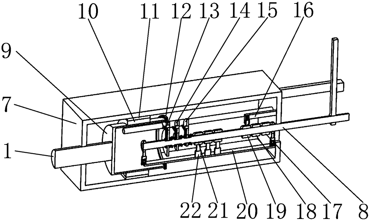
[0052] Such as figure 1 , 2 , 3, it includes an output shaft 1, a locking mechanism 2, a first fixed ring 3, a toggle lever 4, a first fixed plate 5, a support mechanism 6, a first guide block 81, a second guide block 82, a first Three guide blocks 83, fixed shell 7, input shaft 8, first connecting cylinder 9, second fixed ring 10, fixed block 11, third fixed ring 12, first gear 13, second gear 14, third gear 15, L-shaped fixed rod 16, third snap ring 17, second snap ring 18, first snap ring 19, second fixed plate 20, guide groove 23, fixed round hole 24, accommodation cavity 25, movement slot 26, fourth gear 27. The fifth gear 28, the sixth gear 29, the guide column 30...


PUM


Abstract

The invention belongs to the technical field of gear transmission gearboxes, and particularly relates to a gear transmission gearbox with a gear collision preventing function. The gear transmission gearbox comprises an output shaft, a position clamping mechanism, a first fixing ring, a stirring rod, a first fixing plate, a supporting mechanism, a first guide block, a second guide block, a third guide block, a fixing shell, an input shaft, a first connecting barrel, a second fixing ring, a fixing block, a third fixing ring and the like, wherein the fixing shell is provided with a containing cavity. A penetration fixing circular hole is formed in the side face of the containing cavity. The side face, opposite to the fixing circular hole, of the containing cavity is provided with a penetration motion groove. Two first guide grooves are symmetrically formed in the outer circle face of the input shaft. Two third guide grooves are symmetrically formed in the outer circle face of the input shaft. By means of the gear transmission gearbox, when a gear rotating at the low speed is forcibly plugged into a gear rotating at the high speed or the gear rotating at the high speed is forcibly plugged into the gear rotating at the low speed, the phenomenon of gear collisions in the gearbox can be avoided.

Description

technical field [0001] The invention belongs to the technical field of gear transmission gearboxes, and in particular relates to a gear transmission gearbox with the function of preventing tooth punching. Background technique [0002] At present, the existing gear transmission gearboxes often cause damage to the gearbox gears due to the user's misoperation. As far as automobile gearboxes are concerned, it is generally required to step on the clutch to the bottom during manual shifting, and then perform gear shifting operations. When the speed is basically the same, loosen the clutch and complete the gear shift. When the engine speed does not match the wheel speed, not only will there be gear noises when the user shifts gears, but it will also easily cause gear hitting. If the gear is forcibly inserted into a high-speed rotating gear, the phenomenon of tooth beating will definitely occur. In order to avoid this kind of situation, it is very necessary to design a gear transmis...

Claims


Application Information

Patent Timeline
IPC IPC(8): F16H3/083F16H57/021F16H57/023
CPCF16H3/083F16H57/021F16H57/023F16H2057/02043
Inventor 胡凡黄银凤
Owner 柳欢
Learn More