Self-locking mechanism of synchronizer

A synchronizer and self-locking technology, which is applied to clutches, mechanical equipment, mechanical drive clutches, etc., can solve problems such as reducing synchronizer self-locking, synchronizer damage, and shortening the effective compression distance of springs, so as to prevent synchronizer damage and improve Self-locking ability, avoiding unreliable self-locking effect

Inactive Publication Date: 2015-12-23
SHAANXI FAST AUTO DRIVE GROUP CO LTD
View PDF7 Cites 1 Cited by
  • Summary
  • Abstract
  • Description
  • Claims
  • Application Information

AI Technical Summary

Problems solved by technology

[0002] The existing synchronizer spring is a cylindrical helical spring, and its end face only contacts with the side of the cylindrical low-grade locking pin at two points. Since the force generated after the spring is compressed is relatively large, and the general hardness of the spring is greater than that of the side of the low-grade locking pin, it will cause There is a pit on the side of the low-grade locking pin. With the use of the synchronizer, the pit gradually becomes larger, shortening the effective compression distance of the spring, which will reduce the self-locking force of the synchronizer, so that the lock of the synchronizer is unreliable. During the synchronization process, tooth beating phenomenon occurs, and the synchronizer is damaged.

Method used


Image

  • Self-locking mechanism of synchronizer
  • Self-locking mechanism of synchronizer
  • Self-locking mechanism of synchronizer

Examples


Embodiment Construction

[0026] Below in conjunction with accompanying drawing, the present invention is described in further detail:

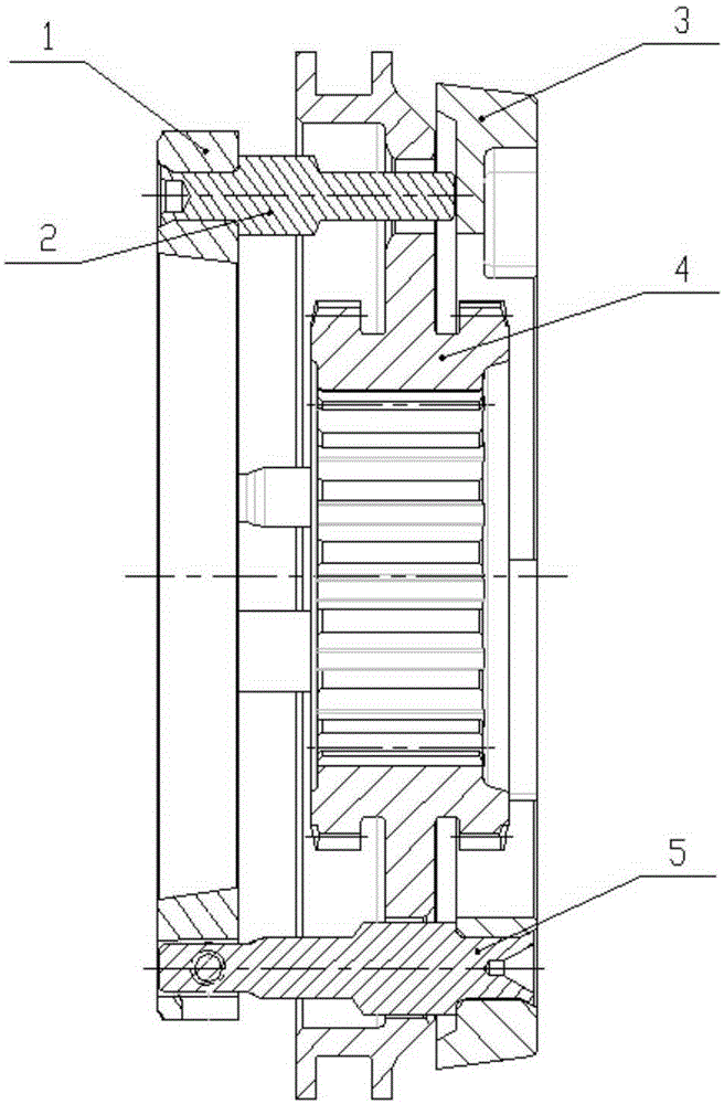
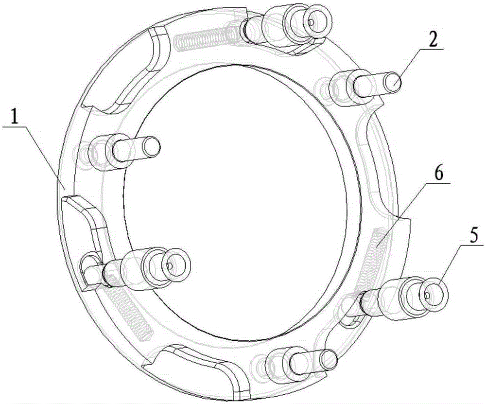
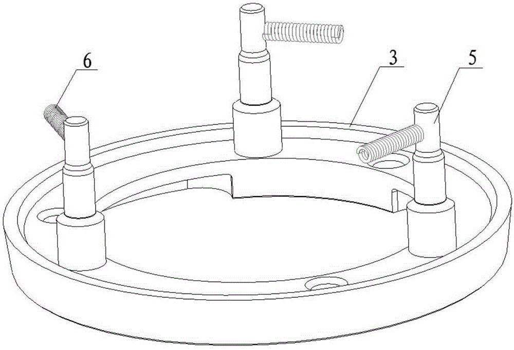
[0027] see Figure 1 to Figure 7 , a synchronizer self-locking mechanism, comprising a high-grade cone ring 1 and a low-grade cone ring 3, three high-grade locking pins 2 are interspersed on the high-grade cone ring 1, and three low-grade locking pins 5 are interspersed on the low-grade cone ring 3, There is a sliding gear sleeve 4 between the high-grade cone ring 1 and the low-grade cone ring 3. There are two groups of holes on the sliding gear sleeve 4, a total of six, three holes at intervals form a group, and the two groups of holes are not equally distributed. , respectively set the high-grade lock pin 2 and the low-grade lock pin 5, and the high-grade cone ring 1 is provided with three springs 6 that cooperate with the low-grade lock pin 5 in the circumferential direction. 5. One end of the force transmission area is tightly folded into the embedded spring 6-1 ...


PUM


Abstract

The invention discloses a self-locking mechanism of a synchronizer. The self-locking mechanism comprises a high-gear conical ring and a low-gear conical ring. High-gear locking pins are inserted in the high-gear conical ring in a penetrating manner. Low-gear locking pins are inserted in the low-gear conical ring in a penetrating manner. A sliding gear sleeve is arranged between the high-gear conical ring and the low-gear conical ring and provided with two sets of holes. The two sets of holes are distributed in a non-equal manner, and the high-gear locking pins and the low-gear locking pins are sleeved with the two sets of holes respectively. Springs matched with the low-gear locking pins are arranged in the circumferential direction of the high-gear conical ring. The springs are embedded springs or disc springs with cylinders, wherein the force transmission area of the springs and the low-gear locking pins can be increased, and one ends of the springs are closely folded. Or, ejector pins capable of increasing the force transmission area of the springs and the low-gear locking pins are arranged between the springs and the low-gear locking pins. The phenomenon that gear colliding happens in the process that the synchronizer loses synchronization due to unreliable self-locking can be avoided, and the synchronizer is prevented from being damaged.

Description

technical field [0001] The invention relates to a self-locking mechanism, in particular to a synchronizer self-locking mechanism. Background technique [0002] The existing synchronizer spring is a cylindrical helical spring, and its end face only contacts with the side of the cylindrical low-grade locking pin at two points. Since the force generated after the spring is compressed is relatively large, and the general hardness of the spring is greater than that of the side of the low-grade locking pin, it will cause There is a pit on the side of the low-grade locking pin. With the use of the synchronizer, the pit gradually becomes larger, shortening the effective compression distance of the spring, which will reduce the self-locking force of the synchronizer, so that the lock of the synchronizer is unreliable. During the synchronization process, the tooth beating phenomenon occurs, and the synchronizer is damaged. Contents of the invention [0003] The purpose of the prese...

Claims


Application Information

Patent Timeline
Patent Type & Authority Applications(China)
IPC IPC(8): F16D23/02
Inventor 魏小强李建峰
Owner SHAANXI FAST AUTO DRIVE GROUP CO LTD
Why Eureka
Try Eureka