Gas pollution monitoring instrument

A technology for monitoring instruments and gas pollution, applied in instruments, scientific instruments, and analyzing gas mixtures, etc., can solve problems such as uneven pollutant content and inaccurate air monitoring, and achieve the effect of solving uneven pollutant content

Active Publication Date: 2018-09-28
安徽相恒气体科技有限公司
View PDF11 Cites 2 Cited by
  • Summary
  • Abstract
  • Description
  • Claims
  • Application Information

AI Technical Summary

Problems solved by technology

[0003] The purpose of the present invention is to provide a gas pollution monitoring instrument. Through the main air pipe and the base, the two side air intake pipes can simultaneously sample the air in the windward direction and the leeward direction; The air sample with homogeneous wind avoids the influence of wind force on the collection of air samples, which effectively solves the problem of uneven pollutant content in air samples in the windward and leeward directions and inaccurate air monitoring; through the spring and the ring-shaped trachea cover, it can be mixed The air is sealed to maximize the retention of sufficient air samples, and at the same time, it can ensure that the air samples in the windward direction and the leeward direction are collected and mixed at the same time.

Method used


Image

  • Gas pollution monitoring instrument
  • Gas pollution monitoring instrument
  • Gas pollution monitoring instrument

Examples


specific Embodiment approach 1

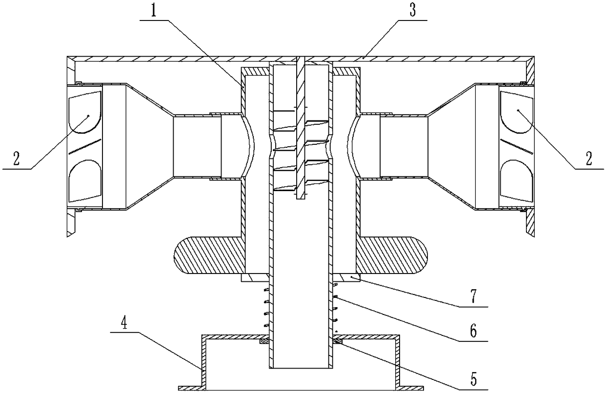
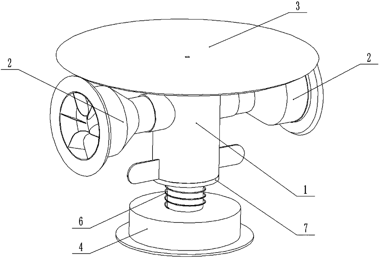
[0024] Combine below Figure 1-8 Describe this embodiment, a gas pollution monitoring instrument, including a main air pipe 1, a side air inlet pipe 2, a mixed flow assembly 3 and a base 4, the left and right ends of the main air pipe 1 are fixedly connected with side air inlet pipes 2, and the mixed flow The component 3 is rotatably connected to the upper end of the main air pipe 1, and the two side air intake pipes 2 are connected to the mixed flow assembly 3 through gear transmission, and the main air pipe 1 is rotatably connected to the base 4; The side air inlet pipes 2 face the windward direction and the leeward direction respectively; the side air inlet pipe 2 in the windward direction is affected by the wind force to realize the active rotation of the impeller 2-2, and the mixed flow component 3 drives the impeller 2-2 in the leeward direction to rotate, and the impeller 2 in the leeward direction -2 rotates so that the air in the leeward direction passes into the main...

specific Embodiment approach 2

[0025] Combine below Figure 1-8 Describe this embodiment, this embodiment will further explain Embodiment 1, the lower end of the main air pipe 1 is fixedly connected to the limit snap ring 5, the limit snap ring 5 is located at the lower end of the base 4, and the main air pipe 1 slides An annular trachea cover 7 is connected, a spring 6 is arranged between the annular trachea cover 7 and the base 4, and the upper end surface of the annular trachea cover 7 fits with the main air pipe 1; it enters the main air pipe 1 through two side air intake pipes 2 The air inside is mixed in the air mixing pipe 1-2 and transported downward along the air mixing pipe 1-2 to provide the air samples required for air monitoring; when the wind speed is high, the outer casing 1-1 and the air mixing pipe 1 There is more air between -2, at this time, the air pressure between the outer tube 1-1 and the gas mixing tube 1-2 increases, the annular trachea cover 7 presses down and slides, the spring 6 ...

specific Embodiment approach 3

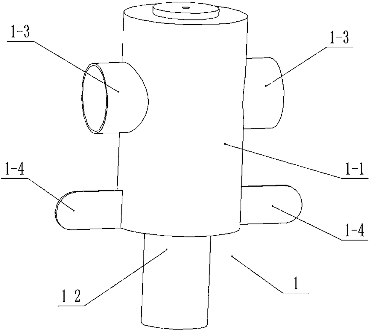
[0026] Combine below Figure 1-8 Describe this embodiment, this embodiment will further explain the second embodiment, the main air pipe 1 includes the main air pipe 1 including the outer tube 1-1, the gas mixing pipe 1-2, the measuring tube joint 1-3, the wind deflector 1- 4. Partition plate 1-5 and gas mixing hole 1-6, the gas mixing tube 1-2 is fixedly connected in the outer casing 1-1, and the left and right ends of the outer casing 1-1 are fixedly connected with the measuring tube joint 1 -3, the left and right ends of the lower end of the outer casing 1-1 are fixedly connected with wind deflectors 1-4, and the front and rear ends between the outer casing 1-1 and the gas mixing pipe 1-2 are fixedly connected with partitions. Plate 1-5, the left and right ends of the partition 1-5 form an air intake cavity, the left and right ends of the gas mixing pipe 1-2 are provided with gas mixing holes 1-6, and the gas mixing holes 1-6 and The measuring pipe joints 1-3 are arranged ...


PUM


Abstract

The invention relates to the technical field of gas pollution monitoring, in particular to a gas pollution monitoring instrument. The gas pollution monitoring instrument comprises a main gas pipe, lateral gas inlet pipes, a mixed flow assembly and a base, wherein the lateral gas inlet pipes are fixedly connected to the left end and the right end of the main gas pipe respectively; the mixed flow assembly is rotationally connected at the upper end of the main gas pipe; both the lateral gas inlet pipes are in transmission connection with the mixed flow assembly through a gear; the main gas pipe is rotationally connected on the base. According to the gas pollution monitoring instrument, through the main gas pipe and the base, the two lateral gas inlet pipes can simultaneously sample air in thewindward direction and the leeward direction; by simulating windless and homogeneous air samples, it is avoided that wind power influences on collection of the air samples, and the problems that thepollutant content of the air samples in the windward direction and the leeward direction is uneven, and air monitoring is inaccurate are effectively solved; mixed air can be sealed, sufficient air samples are furthest reserved, and meanwhile it can be guaranteed that the air samples in the windward direction and the leeward direction are collected and mixed at the same time.

Description

technical field [0001] The invention relates to the technical field of gas pollution monitoring, in particular to a gas pollution monitoring instrument. Background technique [0002] For example, the patent application number is CN201620257483.8, a multi-functional harmful gas monitor, which includes a shelf, a harmful gas monitor and a temperature and humidity monitor. Connected to the base, the charging end of the harmful gas monitor is connected to the charging base, the top of the harmful gas monitor is provided with a fixed card slot corresponding to the temperature and humidity monitor, and the temperature and humidity monitor is connected to the harmful gas through the fixed card slot. The monitor is connected, and the top of the harmful gas monitor is connected with a miniature LED lighting lamp, and the miniature LED lighting lamp is connected with the harmful gas monitor with an electric line, and the bottom of the harmful gas monitor is connected with a working pr...

Claims


Application Information

Patent Timeline
Patent Type & Authority Applications(China)
IPC IPC(8): G01N33/00
CPCG01N33/0004
Inventor 陈昌彬
Owner 安徽相恒气体科技有限公司
Why Eureka
Try Eureka