Rotary wire connector

A connector, rotary technology, applied in the direction of flexible/rotatable wire connectors, connections, contact parts, etc., can solve problems such as twisting deformation and breaking of cables or wires

Inactive Publication Date: 2018-09-28
XINJIANG BAYI IRON & STEEL
View PDF3 Cites 6 Cited by
  • Summary
  • Abstract
  • Description
  • Claims
  • Application Information

AI Technical Summary

Problems solved by technology

[0003] The purpose of the present invention is to provide a rotary connector, which can solve the problem of being twisted, deformed, and broken due to the inab

Method used


Image

  • Rotary wire connector
  • Rotary wire connector

Examples


Embodiment Construction

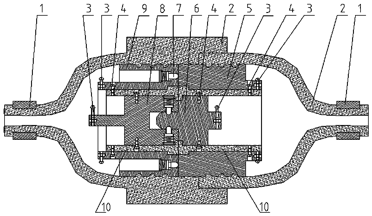
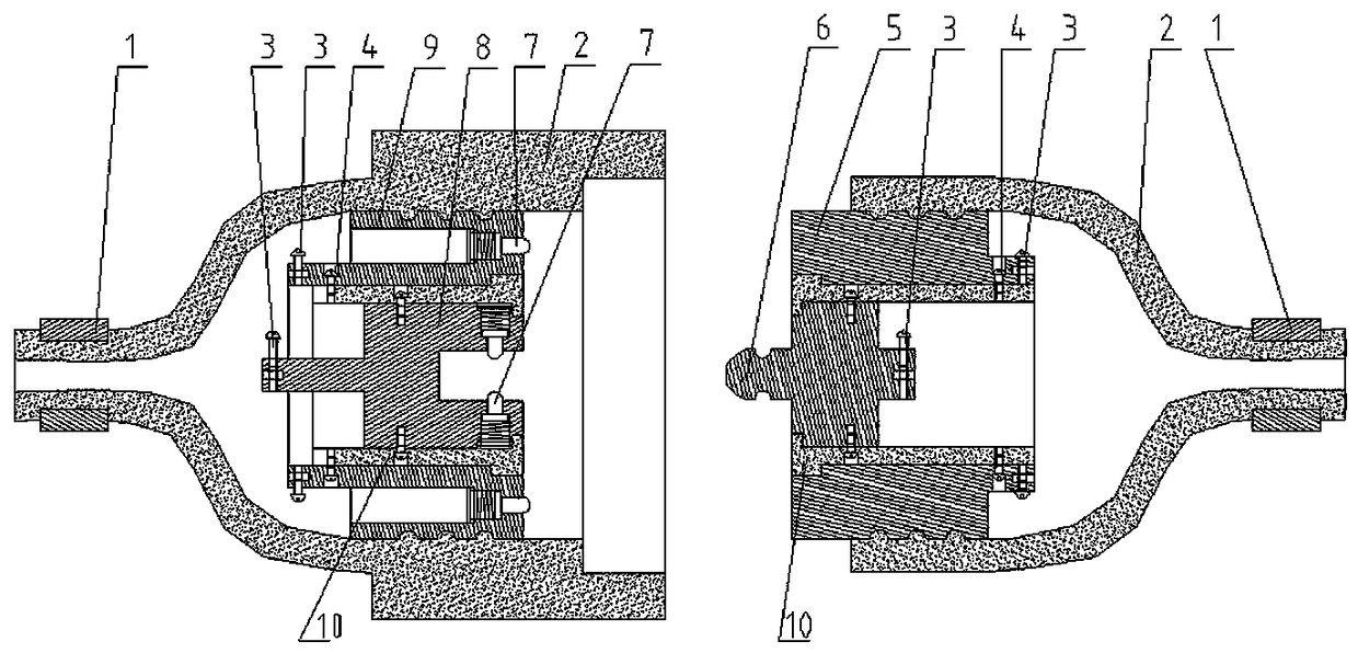
[0009] Such as figure 1 , figure 2 As shown, the rotary connector of the present invention mainly includes a sheath 2 . The two trumpet-shaped sheaths 2 that can be inserted into each other are respectively equipped with an annular plug end 5, a cylindrical plug end 6, a terminal post 3, a positioning stud 4, an annular socket end 9, a cylindrical socket end 8, a terminal post 3, Locating stud 4, spring post 7. An insulating sleeve 10 is installed between the annular plug end 5 and the cylindrical plug end 6 , the annular socket end 9 and the cylindrical socket end 8 . There is an annular groove at the corresponding contact position between the cylindrical plug end 6 and the elastic post 7 . Tightening straps 1 are installed at both ends of the sheath 2 .

[0010] Such as figure 1 , figure 2 As shown, when making and using the present invention, in order to make the sheath 2 firmly connected with the annular plug end 5 or the annular socket end 9 and not easy to diseng...


PUM


Abstract

The invention discloses a rotary wire connector, which is mainly used for being connected on a cable and rotating relatively to prevent the cable from being twisted to deform and fracture. The rotarywire connector mainly comprises a ring-shaped plug end, a columnar plug end, a ring-shaped socket end, a columnar socket end and a sheath, and can relatively rotate in a good power-up state mainly bycorrespondingly inserting the ring-shaped socket end and the columnar socket end at the ring-shaped plug end of which two half body structures comprise the sheath and an insulating bush, and the columnar plug end. After using the rotary wire connector, a problem that the cable or a wire cannot rotate relatively and consequently is twisted to deform and fracture in the existing technology can be solved, and the rotary wire connector also can be used for electrical equipment which also require the cable to rotate relatively.

Description

technical field [0001] The invention relates to a rotary connector. Background technique [0002] The connectors in the prior art cannot make the wires or cables at both ends to rotate relative to each other, and the problems that the cables are twisted, deformed and broken are prone to occur. Contents of the invention [0003] The purpose of the present invention is to provide a rotary connector, which can solve the problem of torsion, deformation and breakage caused by the inability of relative rotation of cables or wires in the prior art, and can also be used for electrical equipment that requires relative rotation of cables. [0004] A rotary connector of the present invention mainly includes a sheath, and two trumpet-shaped sheaths that can be inserted into each other are respectively equipped with an annular plug end, a cylindrical plug end, a terminal post, a positioning stud, and an annular socket. end, cylindrical socket end, terminal, positioning stud, spring po...

Claims


Application Information

Patent Timeline
IPC IPC(8): H01R13/20H01R13/52H01R13/58H01R24/00H01R24/20H01R24/28H01R35/04H01R13/04H01R13/10
CPCH01R35/04H01R13/04H01R13/10H01R13/20H01R13/5205H01R13/5812H01R24/005H01R24/20H01R24/28
Inventor 任超
Owner XINJIANG BAYI IRON & STEEL
Why Eureka
Try Eureka