Disassembling tool for disconnecting link clamping spring

A technology of clamping springs and knife switches, which is applied in the direction of switchgear, electrical components, etc., can solve problems such as tilting of the ejector rod, low disassembly success rate, and injuries caused by people falling down, so as to achieve stable force, improve stability, and avoid installation The effect of the accident

Inactive Publication Date: 2018-09-28
廊坊市东电腾达电力工程有限公司
View PDF2 Cites 0 Cited by
  • Summary
  • Abstract
  • Description
  • Claims
  • Application Information

AI Technical Summary

Problems solved by technology

The disassembly success rate of this method is low, and the ejector rod is prone to tilting. It needs repeated operations to complete the disassembly, and people may fall and be injured.

Method used


Image

  • Disassembling tool for disconnecting link clamping spring

Examples


Embodiment Construction

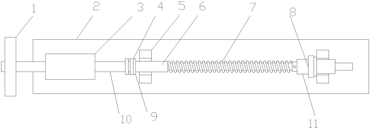
[0013] figure 1 It is a structural schematic diagram of the present invention; as shown in the figure, the knife gate clamping spring 7 disassembly tool of the present embodiment includes a horizontal support, screw mandrel 10 nuts 3 pairs, thrust bearing 4 components and linear bearing 8 components; the horizontal The bracket includes a base plate 2 and two support slots 5 fixed on the base plate 2 for supporting the knife switch; the screw 10 nut 3 pair includes a nut 3 fixed on the base plate 2 and the Cooperating screw rod 10; the thrust bearing 4 assembly is arranged at the end of the screw rod 10 for pushing one end of the knife gate ejector rod 6; the linear bearing 8 assembly is used to cover the ejector rod 6 and is used to support the spring 7 and the support slot 5; the ejector rod 6 and the spring 7 are supported by a horizontal bracket, which can improve the stability of the clamping spring 7 during disassembly. The spring 7, the screw rod 10 and the nut 3 mechan...


PUM


Abstract

The invention discloses a disassembling tool for a disconnecting link clamping spring. The disassembling tool comprises a horizontal bracket, a lead screw nut pair, a thrust bearing assembly and a linear bearing assembly; the horizontal bracket comprises a bottom plate and two support clamping grooves fixed in the bottom plate and used for supporting a disconnecting link; the lead screw nut pair comprises a nut fixed on the bottom plate and a lead screw matched with the nut; the thrust bearing assembly is arranged on the end part of the lead screw and used for pushing one end of a disconnecting link ejector rod; and the linear bearing assembly is used for being arranged on the ejector rod in a sleeving manner and jacking between the spring and the support clamping grooves. By adopting thetool to disassemble the disconnecting link, stability and reliability are achieved, low labor intensity of an operator is realized, and falling over of the operator can be avoided effectively.

Description

technical field [0001] The invention belongs to the field of maintenance tools for electric equipment, and in particular relates to a tool for dismantling a clamping spring of a knife switch. Background technique [0002] At present, the GW16 type (single-column single-arm vertical telescopic type) knife switch (hereinafter referred to as the 16-type knife switch) is widely used to isolate the overhauled equipment from the live bus or switch the unloaded bus. However, after the equipment has been in operation for a long time, the clamping spring in the knife switch is corroded and aged. This will cause the clamping force of the knife switch to weaken, the contact resistance to increase, and the equipment to overheat or even burn out; at this time, the knife switch needs to be disassembled and overhauled, and the clamping spring needs to be maintained or replaced. After the clamping spring is compressed, it is fixed on the push rod by the limit pin. Therefore, regardless of...

Claims


Application Information

Patent Timeline
Patent Type & Authority Applications(China)
IPC IPC(8): H02B3/00
CPCH02B3/00
Inventor 周成敏岳云凤张涛赵德才徐凤龙
Owner 廊坊市东电腾达电力工程有限公司
Why Eureka
Try Eureka