Caving device and caving equipment

A technology for pits and mounting frames, which is applied in the field of pitting devices and pitting equipment, can solve the problems of large pit errors, time-consuming work, and low work efficiency, and achieve the effects of small size errors, improved work efficiency, and error avoidance

Inactive Publication Date: 2018-10-02
ZHANGYE ACAD OF AGRI SCI
View PDF7 Cites 0 Cited by
  • Summary
  • Abstract
  • Description
  • Claims
  • Application Information

AI Technical Summary

Problems solved by technology

[0005] The purpose of the present invention is to provide a kind of hole digging device to solve the technical problems existing in the prior art that manual digging is adopted, the error of the pit is large, manual re-displacement is required, time-consuming work is required, and the work efficiency is low.
[0006] The present invention also provides a hole digging device to solve the technical problems of labor time-consuming and low work efficiency in the prior art.

Method used


Image

  • Caving device and caving equipment
  • Caving device and caving equipment
  • Caving device and caving equipment

Examples


Embodiment 1

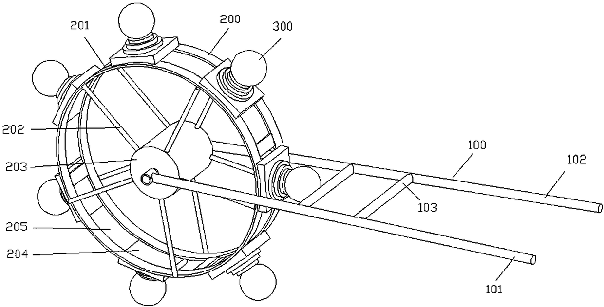
[0043] figure 1 It is a schematic structural diagram of the first cavitation device provided by the embodiment of the present invention.

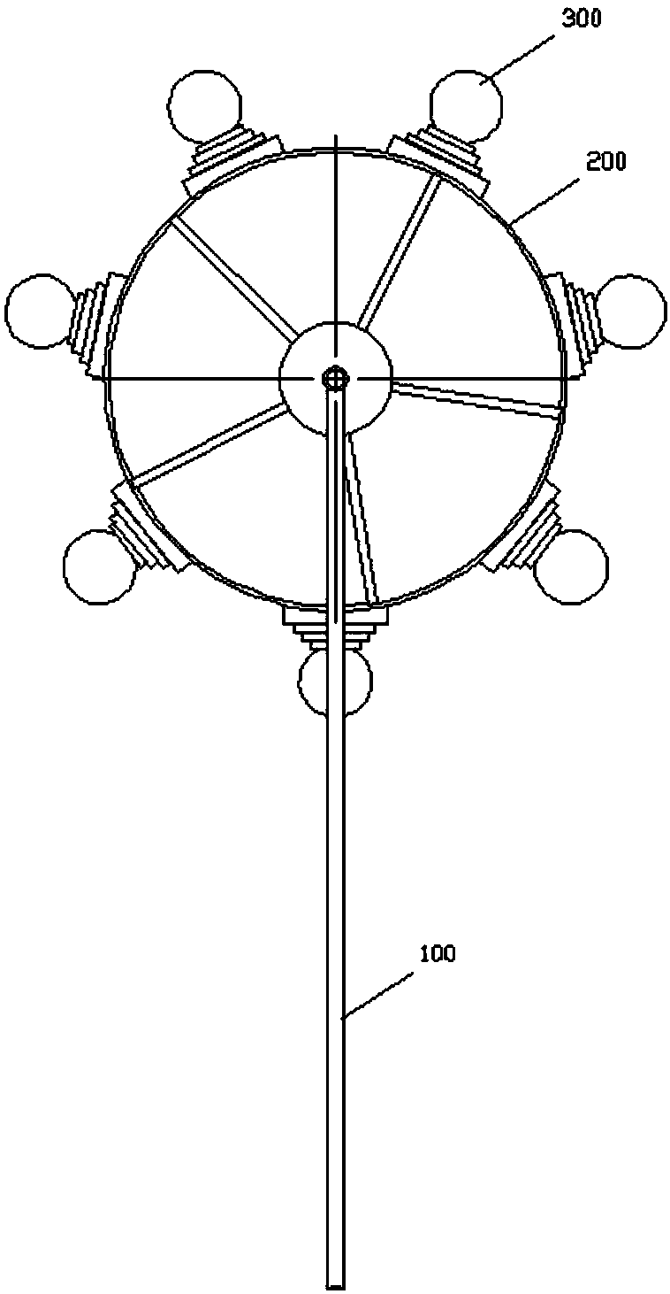
[0044] Such as figure 1 As shown, a cavitation device provided by the present invention includes a push frame 100, a rotating frame 200 and a cavitation ball 300;

[0045] One end of the pushing frame 100 is used for holding by the user's hand, and the other end of the pushing frame 100 is connected with the rotating frame 200, and can push the rotating frame 200 to rotate;

[0046] The number of the cavitation balls 300 is multiple, and the cavitation balls 300 are connected to the rotating frame 200;

[0047] The pushing frame 100 pushes the rotating frame 200 to perform a rotating movement, and the rotating frame 200 can drive the hole-raising ball 300 to punch out holes on the field.

[0048] exist figure 1 Among them, the right end of the push frame 100 is used for the user's hands to hold, the left end of the push frame 100 is con...

Embodiment 2

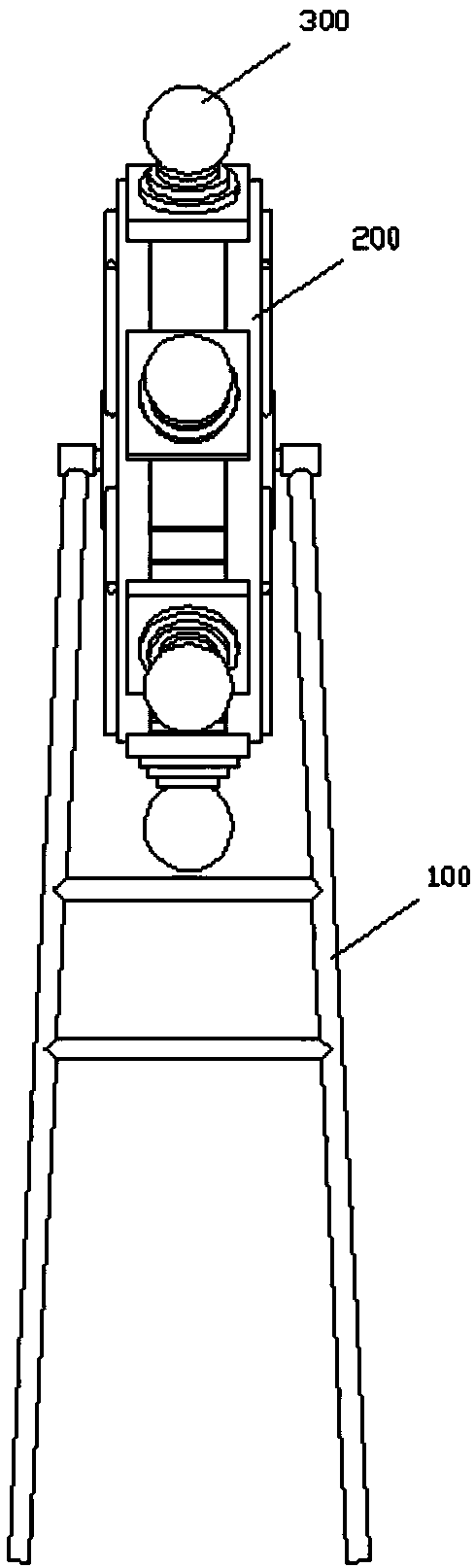
[0057] Figure 7 It is a schematic structural diagram of the second cavitation device provided by the embodiment of the present invention.

[0058] Further, the pushing frame 100 includes a first holding rod 101, a second holding rod 102 and a connecting rod 103;

[0059] One end of the first holding rod 101 is connected to one side of the rotating frame 200, and the other end of the first holding rod 101 is provided with a first holding groove 104, and the first holding groove 104 is used for It is held by one hand of the user; one end of the second holding rod 102 is connected to the other side of the rotating frame 200, and the other end of the second holding rod 102 is provided with a second holding groove 105, the second holding groove 105 is used for holding by the user's other hand;

[0060] One end of the connecting rod 103 is connected to the first gripping rod 101, and the other end of the connecting rod 103 is connected to the second gripping rod 102; the connecti...


PUM


Abstract

The invention provides a caving device and caving equipment, and relates to the technical field of caving tool. The caving device includes a pushing frame, a rotating frame and caving balls; one end of the pushing frame is used for a user hand to hold, the other end of the pushing frame is connected with the rotating frame, and the rotating frame can be pushed for rotating motion; a plurality of the caving balls are arranged, and the plurality of the caving balls are connected with the rotating frame; the pushing frame pushes the rotating frame to rotatingly move; the rotating frame can drivethe caving balls to smash caving pits in the field. The technical problems of large error, working time wasting and low working efficiency with a manual excavation method in the prior art are solved.The pushing frame can push the rotating frame to rotatingly move and provides the pushing force for the rotating frame, and the rotating frame can drive the caving balls to smash the caving pits in the field, so the size error of the caving pits is small, and the work efficiency is improved.

Description

technical field [0001] The invention relates to the technical field of cavitation tools, in particular to a cavitation device and cavitation equipment. Background technique [0002] Planting is the main part of agriculture. It refers to using land as the basic means of production and using the biological functions of crops to convert solar energy into chemical potential and agricultural products. The planting industry uses land as an important means of production, uses green plants, and synthesizes carbon dioxide, water, and minerals in nature into organic substances through photosynthesis, and at the same time, converts solar energy into chemical energy and stores it in organic substances. Therefore, the planting industry is the material source of all plant products as food, and also the material basis of human life activities. Planting is an important foundation of large-scale agriculture. It is not only the main source of food and means of subsistence for human beings, b...

Claims


Application Information

Patent Timeline
Patent Type & Authority Applications(China)
IPC IPC(8): A01C5/02
CPCA01C5/02
Inventor 刘占鑫
Owner ZHANGYE ACAD OF AGRI SCI
Why Eureka
Try Eureka