Sealing structure and dust collector comprising same

A technology of sealing structure and vacuum cleaner, which is applied in the direction of vacuum cleaners, suction filters, cleaning equipment, etc., can solve the problem of micro switch contact damage and other problems, and achieve a good sealing effect

Pending Publication Date: 2018-10-02
SKYBEST ELECTRIC APPLIANCE SUZHOU CO LTD
View PDF1 Cites 2 Cited by
  • Summary
  • Abstract
  • Description
  • Claims
  • Application Information

AI Technical Summary

Problems solved by technology

However, the vacuum cleaner of the above technical solution has the problem that dust and impurities enter the micro switch t

Method used


Image

  • Sealing structure and dust collector comprising same
  • Sealing structure and dust collector comprising same
  • Sealing structure and dust collector comprising same

Examples


no. 1 approach

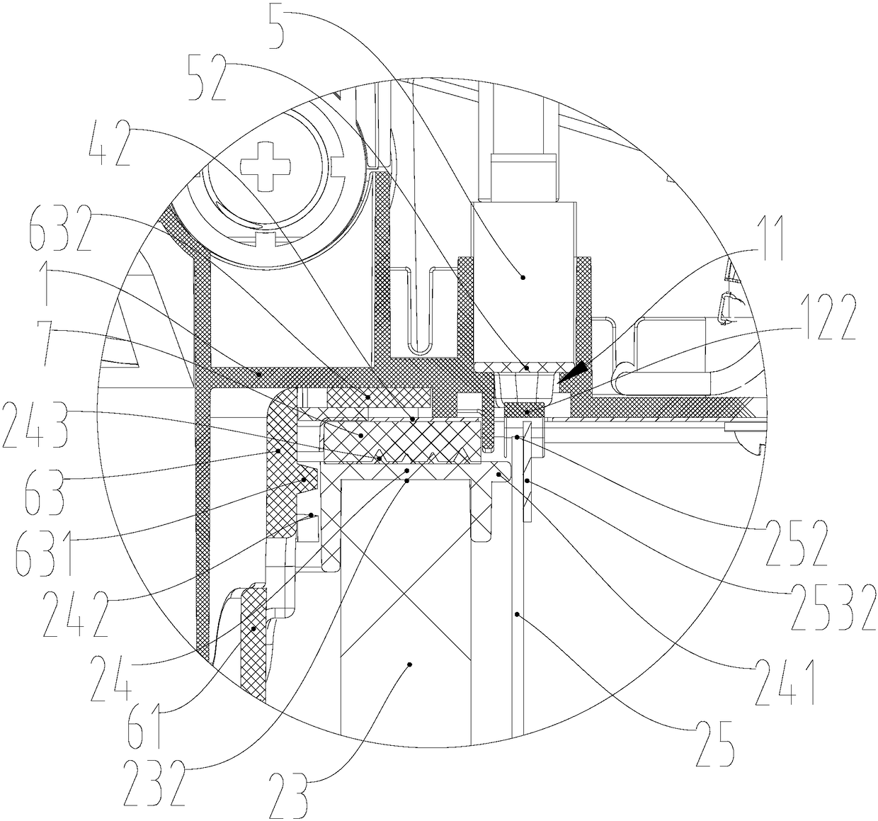
[0038] In this embodiment, as shown in FIGS. 2 to 9 , an elastic arm 121 is provided in the through hole 11 . One end of the elastic arm 121 is provided with an indenter 1211, the thickness of the indenter 1211 is obviously greater than the thickness of the elastic arm 121, specifically, the indenter 1211 protrudes downward, and in other embodiments, the indenter 1211 protrudes upward; The other end of 121 is connected to the inner wall of the through hole 11. Specifically, the elastic arm 121 is integrally formed with the windshield 1. Since the elastic arm 121 itself is made of elastic material, the pressure head 1211 can move up and down along the axial direction of the through hole 11. Specifically, when pressure is applied, the pressure head 1211 moves along the pressure direction; when the pressure is released, the pressure head 1211 resets under the action of the elastic arm 121 . In some other embodiments, the elastic arm 121 is elastically pivoted to the inner wall of...

no. 2 approach

[0051]In this embodiment, as shown in FIG. 10 , the windshield 1 further includes a linkage part 9, and the linkage part 9 includes an abutment 91 arranged on the upstream side of the windshield 1 and a trigger 92 hinged to the middle of the abutment 91. The trigger 92 moves in the through hole 11 along its axial direction. Specifically, both the abutting piece 91 and the triggering piece 92 are rod-shaped. The first end 911 of the abutting member 91 corresponds to the installation position of the first filter 23 , and the second end 912 of the abutting member 91 corresponds to the installation position of the second filter 25 . The first end 921 of the trigger member 92 is pivotally connected to the middle part of the abutment member 91 through the pivot 93 , and slide grooves 923 are symmetrically arranged on both sides of the middle part of the trigger member. A symmetrical third protrusion 111 extends toward the center of the through hole 11 from the position correspondin...


PUM


Abstract

The invention discloses a sealing structure. The sealing structure comprises a separating body, an accommodating groove, a state sensor (5) and a first sealing piece (52), wherein one side of the separating body is a clean region while the other side of the separating body is a polluted region; the separating body is provided with a through hole (11) which penetrates through the clean region and the polluted region; the accommodating groove is formed in the clean region; the state sensor (5) is mounted in the accommodating groove and comprises a contact; the contact faces the through hole (11); and the first sealing piece (52) is an elastic material, and is arranged between the contact and the through hole (11). The invention further discloses a dust collector comprising the sealing structure. By the sealing structure, the circumstance that dust impurities of the outside enter a position nearby a contact of a microswitch to enable the microswitch to be damaged and fail can be preventedeffectively.

Description

technical field [0001] The invention relates to a sealing structure, in particular to a sealing structure of a state sensor. The invention also relates to a vacuum cleaner comprising the sealing structure. Background technique [0002] In the prior art, there are vacuum cleaners that use at least one micro switch to sense whether the filter is installed, such as Chinese patent CN106073638A. However, during use of the vacuum cleaner of the above technical solution, there is a problem that dust and impurities enter the micro switch through the through hole provided between the micro switch and the filter, resulting in damage to the contacts of the micro switch. Contents of the invention [0003] The purpose of the present invention is to solve the defects in the prior art and provide a sealing structure capable of effectively avoiding dust leakage. [0004] The technical solution of the present invention is a sealing structure, comprising: a partition body, one side of the...

Claims


Application Information

Patent Timeline
IPC IPC(8): A47L9/14
CPCA47L9/1454
Inventor 刘海平孔钊夏亮
Owner SKYBEST ELECTRIC APPLIANCE SUZHOU CO LTD
Why Eureka
Try Eureka