A converter control unit protection device and method

A control unit and protection device technology, applied in the direction of output power conversion devices, instruments, electrical components, etc., can solve the damage and failure of external converter modules, misoperation of product storage devices, lack of effective protection mechanisms for converter control units, etc. question

Active Publication Date: 2020-11-20
CSR ZHUZHOU ELECTRIC LOCOMOTIVE RES INST
View PDF5 Cites 0 Cited by
  • Summary
  • Abstract
  • Description
  • Claims
  • Application Information

AI Technical Summary

Problems solved by technology

[0007] In view of this, the object of the present invention is to provide a converter control unit protection device and method to solve the problem that the converter control unit lacks an effective protection mechanism during power-on and power-off processes, and the storage device that comes with the product is prone to being damaged. Misoperation, which leads to technical problems of damage and failure of the external converter module

Method used


Image

  • A converter control unit protection device and method
  • A converter control unit protection device and method
  • A converter control unit protection device and method

Examples


Embodiment 1

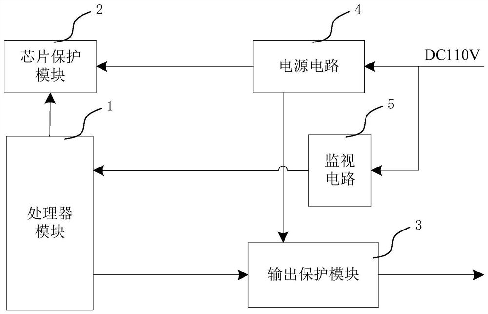
[0079] as attached figure 1 As shown, a specific embodiment of a converter control unit (DCU) protection device includes: a processor module 1 , a chip protection module 2 , an output protection module 3 , a power supply circuit 4 and a monitoring circuit 5 . The power supply circuit 4 converts the external input power into the voltage required inside the converter control unit 100, and the monitoring circuit 5 monitors the external input power (as attached figure 1 110V shown in ), and feeds that power-down status back to processor module 1. The chip protection module 2 and the output protection module 3 monitor the power-on and power-off states of the power supply circuit 4, and perform corresponding protection actions according to the power-on and power-off states. When the processor module 1 receives the power-down information of the external input power supply (110V), the processor module 1 sends the protection logic to the chip protection module 2 and the output protect...

Embodiment 2

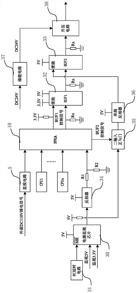
[0100] Because part of the external 110V power supply power-off signal needs to be isolated, it brings complexity to the design, and the power supply module 4 is generally powered off first by the 24V power supply after conversion, so the technical solution in this embodiment can be simplified as a direct Monitor the converted 24V voltage of the power module 4, as attached Figure 5 shown.

[0101] as attached Figure 5 As shown, another specific embodiment of a converter control unit protection device includes: a processor module 1 , a chip protection module 2 , an output protection module 3 , a power supply circuit 4 and a monitoring circuit 5 . The power supply circuit 4 converts the external input power into the voltage required by the converter control unit 100 . The monitoring circuit 5 monitors the power-off status of the output voltage of the power supply circuit 4 and feeds back the power-down status to the processor module 1 . The chip protection module 2 and the o...

Embodiment 3

[0105] A specific embodiment of a method for protecting a converter control unit based on the device described in Embodiment 1, comprising the following steps:

[0106] A1) The power circuit 4 converts the external input power into the voltage required inside the converter control unit 100, and the monitoring circuit 5 monitors the power-down state of the external input power, and feeds back the power-down state to the processor module 1;

[0107] B1) The chip protection module 2 and the output protection module 3 monitor the power-on and power-off states of the power supply circuit 4, and perform corresponding protection actions according to the power-on and power-off states;

[0108] C1) When the processor module 1 receives the power-down state of the external input power supply, the processor module 1 sends the protection logic to the chip protection module 2 and the output protection module 3, and the chip protection module 2 and the output protection module 3 perform corre...


PUM


Abstract

The invention discloses a converter control unit protection device and method. A power circuit converts a external input power supply to a voltage required by the internal portion of a DCU, a monitoring circuit monitors a power-down state of the external input power supply and feeds back the power-down state to a processor module. A chip protection module and the output protection module monitor the power-on and power-down states of a power circuit, and the corresponding protection motion is executed according to the states. When the processor module monitors the power-down state of the external input power supply, the protection logic is sent to the chip protection module and the output protection module, and the chip protection module and the output protection module execute the corresponding protection motion. The processor module monitors the loading state of the program itself and transmits the loading state to the output protection module, and the output protection module executes the corresponding protection motion. The converter control unit protection device and method can solve the technical problems that the DCU is short of effective protection in power-up and power-downprocess and the storage device built-in the product is easy to be mis-operated to cause the damaging and failure of the external conversion module.

Description

technical field [0001] The invention relates to the technical field of converter control, in particular to a protection device and method applied to a converter control unit. Background technique [0002] With the increasing integration of electronic products, multi-processor boards have been more and more applied. For example, FPGA has efficient data management capabilities and real-time data communication capabilities, ARM has excellent logic control capabilities, and DSP has powerful mathematical operations and real-time data processing capabilities. It is increasingly common to combine the three for industrial design occasions. In the small systems that come with these processor chips, more and more memory is used. The memory is generally related to the program loading and important data recording of the processor. Once it fails, the consequences of causing the device to fail to start are very serious. For memory devices, effective protection at power-on and power-off t...

Claims


Application Information

Patent Timeline
Patent Type & Authority Patents(China)
IPC IPC(8): H02M1/32G11C16/22
CPCG11C16/225H02M1/32
Inventor 吕阳许峻峰倪大成李雪江李泽泉董平邱岳烽陈俊波李程胡晓东付伟明谭富民
Owner CSR ZHUZHOU ELECTRIC LOCOMOTIVE RES INST
Why Eureka
Try Eureka