
Turbine engine trial running device

A steam turbine and gear technology, which is applied in the field of steam turbine commissioning devices, can solve the problems of the same installation position, the inability to fix the bottom plate of the steam turbine, and the inability of the base to fall, etc., so as to achieve the effect of moving and saving labor.

Active Publication Date: 2018-10-02
浙江辽汽汽轮机有限公司
View PDF6 Cites 4 Cited by
  • Summary
  • Abstract
  • Description
  • Claims
  • Application Information

AI Technical Summary

Problems solved by technology

[0004] When the steam turbine is transported to the test run site, it usually needs to be lifted by the crane before it can be moved. Then the steam turbine can be dropped on the base in the test run site after getting up and down from the drive train, and then the operator passes the bolt through the installation hole on the bottom plate of the steam turbine. And by tightening the nuts, the base of the steam turbine is fixed on the base, and the test run can be carried out; because of the different models of different steam turbines, the size of the base of the steam turbine will be different and the corresponding installation hole positions will also have corresponding differences. However, the installation position of the bolts on the base remains unchanged, so bases of different sizes may not be able to fall into the position of the bolts on the base, and finally the bottom plate of the steam turbine may not be fixed by the bolts on the base

Method used


Image

  • Turbine engine trial running device
  • Turbine engine trial running device
  • Turbine engine trial running device

Examples


Embodiment Construction

[0042] The present invention will be described in further detail below in conjunction with the accompanying drawings.

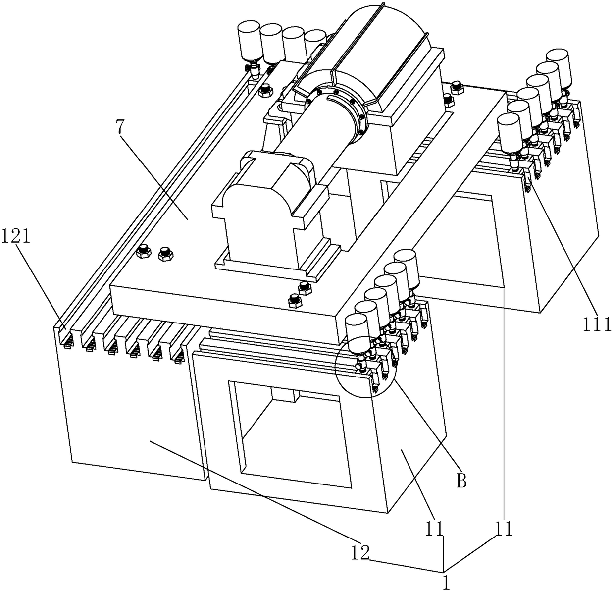
[0043] A test device for a steam turbine, referring to figure 1 , the test device for this steam turbine includes a base 1 and an anchor bolt group 2 arranged on the base 1; wherein the base 1 includes two first seats 11 and one second seat 12, while the two second seats The base body 11 is used to support both ends of the steam turbine bottom plate 7, and a second base body 12 is used to support one side of the steam turbine bottom plate 7. At this time, the support for the entire steam turbine bottom plate 7 can be completed, which is convenient for subsequent adjustment of the steam turbine. The steam turbine body carried on the bottom plate 7 is subjected to a test run test.

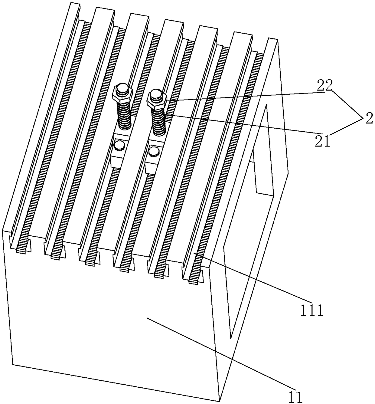
[0044] refer to figure 1 , the first seat body 11 is provided with a plurality of transverse bar-shaped grooves 111 facing horizontally, and the plurality of transverse bar-shaped...


PUM


Abstract

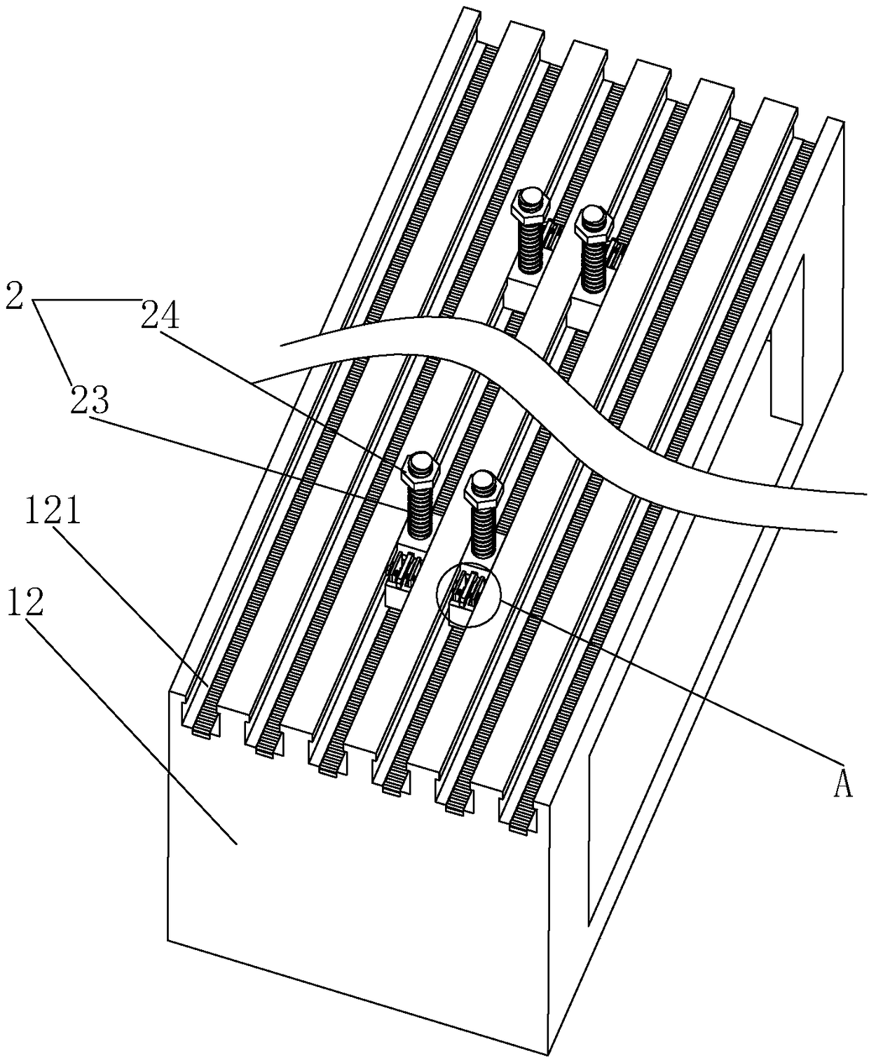
The invention relates to the technical field of turbine engine manufacturing, and discloses a turbine engine trial running device. The turbine engine trial running device comprises a base and a groundbolt set; the base comprises two first base bodies for supporting the two ends of a turbine engine base plate, and a second base body for supporting the side edge of the turbine engine base plate; multiple parallel transverse strip grooves with convex sections are formed in the upper surfaces of the first base bodies; multiple parallel longitudinal strip grooves with convex sections are formed inthe upper surface of the second base body; and the ground bolt set comprises multiple first bolts slidingly connected to the first base bodies and with bolt heads inserted in the transverse strip grooves, first nuts in bolt connection to the first bolts and used for butting against the upper surface of the turbine engine base plate, multiple second bolts slidingly connected to the second base body and with bolt heads embedded in the longitudinal strip grooves, and second nuts in threaded connection with the second bolts and used for butting against the upper surface of the turbine engine baseplate.

Description

technical field [0001] The invention relates to the technical field of steam turbine manufacturing, in particular to a test run device of a steam turbine. Background technique [0002] The steam turbine test run is to check the design, manufacture and construction quality through the whole process of start-up, speed up, constant speed, load and shutdown, to judge whether the parameters such as vibration, temperature and pressure are qualified, and whether each system can work normally; among them, the steam turbine is also called The steam turbine engine is a rotary steam power device. The high-temperature and high-pressure steam passes through the fixed nozzle to become an accelerated air flow and is sprayed on the blades, so that the rotor equipped with blade rows rotates and works externally at the same time; at the same time, the steam turbine is a modern firepower The main equipment of the power plant is also used in the metallurgical industry, chemical industry, and sh...

Claims


Application Information

Patent Timeline
Patent Type & Authority Applications(China)
IPC IPC(8): F01D25/28F01D21/00G01M15/02
CPCF01D21/003F01D25/285F05D2260/83G01M15/02
Inventor 周佳魏巍唐囡赵志义郭琳聂文涛
Owner 浙江辽汽汽轮机有限公司
Learn More