Supercharge Your Innovation With Domain-Expert AI Agents!

A vacuum glue filling method and a vacuum glue filling machine

A technology of glue filling machine and vacuum, which is applied in the field of vacuum glue filling method and vacuum glue filling machine, which can solve the problems of low production efficiency, inaccurate measurement, uncertain pipeline pressure, etc., so as to save time and achieve good glue filling effect , the effect of improving production efficiency

Active Publication Date: 2021-08-13
SHENZHEN XINLUYUAN ELECTRONICS EQUIP CO LTD
View PDF4 Cites 0 Cited by
  • Summary
  • Abstract
  • Description
  • Claims
  • Application Information

AI Technical Summary

Problems solved by technology

However, the vacuum filling efficiency of the above method is very low, and the effect is very unsatisfactory
[0004] In addition, the defoaming module of the existing vacuum glue filling machine only has an umbrella-shaped defoaming tank, so that the glue filling equipment can only be started after the glue is used up every time, and the production efficiency is not high.
The metering pump of the glue mixing module of the existing vacuum glue filling machine passes through the rubber hose and then connects to the dynamic mixing equipment. Because the length of the rubber hose is uncertain and the position of the metering pump is uncertain, the pipeline pressure is uncertain, resulting in inaccurate metering

Method used


Image

  • A vacuum glue filling method and a vacuum glue filling machine
  • A vacuum glue filling method and a vacuum glue filling machine
  • A vacuum glue filling method and a vacuum glue filling machine

Examples


Embodiment Construction

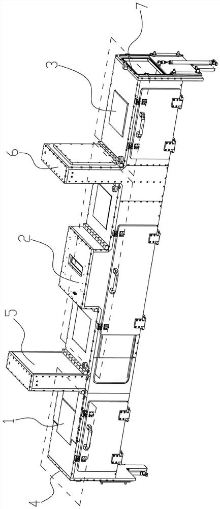
[0051] like figure 1 As shown, the vacuum filling method proposed in the embodiment of the present invention includes the following steps:

[0052] S1. After the product enters the pre-extraction box, door one and door two are closed to vacuumize the pre-extraction box, and then door three is closed to vacuumize the working box;

[0053] S2. After the negative pressure in the pre-pumping box and the working box is balanced, the second door is opened, the product one enters the working box from the pre-pumping box, and then the second door is closed;

[0054] S3. Product 1 begins to pour glue in the working box; at the same time, when the door is opened, the pre-pumping box is evacuated, and then product 2 is put in, then door 1 is closed, and the pre-pumping box is evacuated again; door 4 is closed, and the exhaust Vacuumize the air box. After the negative pressure balance between the exhaust box and the working box and the processing of the product in the working box is comp...


PUM


Abstract

The invention discloses a vacuum glue filling method and a vacuum glue filling machine. The vacuum glue filling method includes the following steps: S1. After the product enters the pre-pumping box, door one and door two are closed, and the pre-pumping box is vacuumed. Then door three is closed, and the working box is evacuated; S2, after the negative pressure in the pre-pumping box and the working box is balanced, door two is opened, and product one enters the working box from the pre-pumping box, and then door two Close; S3, product one starts to pour glue in the working box; at the same time, as soon as the door is opened, the pre-pumping box is evacuated, and then product two is put in, then door one is closed, and the pre-pumping box is evacuated again; door four is closed, Vacuumize the exhaust box. After the negative pressure balance between the exhaust box and the working box and the processing of the product in the working box is completed, the door 3 is opened, and the product enters the exhaust box. Then close the door 3, and then discharge The vacuum of the gas box is released, and the product 1 flows out. At this time, the door 2 is opened, and the product 2 is sent into the working box. The invention improves production efficiency.

Description

technical field [0001] The invention relates to the technical field of vacuum glue filling, and more specifically relates to a vacuum glue filling method and a vacuum glue filling machine. Background technique [0002] Due to the development of electronic technology, the requirements for product packaging are getting higher and higher, and many products require vacuum filling to improve their product performance. [0003] The working process of the traditional vacuum glue filling machine is: open the vacuum box door - enter the product - close the vacuum box door - start vacuuming - reach the preset negative pressure - start working - work is completed - release negative pressure - open the door - product comes out. However, the vacuum filling efficiency of the above method is very low, and the effect is very unsatisfactory. [0004] In addition, the defoaming modules of the existing vacuum glue filling machines only have umbrella-shaped defoaming tanks, so that after each ...

Claims


Application Information

Patent Timeline
Patent Type & Authority Patents(China)
IPC IPC(8): B05D1/26B05D3/04B05C5/02B05C15/00B05C11/10B01F7/18B01F15/02B01F15/04B01D19/00
CPCB01D19/00B05C5/02B05C11/10B05C11/101B05C15/00B05D1/26B05D3/0486B01F27/074B01F27/191B01F27/90B01F35/712B01F35/7176B01F35/882B01F2101/36
Inventor 蔡翔
Owner SHENZHEN XINLUYUAN ELECTRONICS EQUIP CO LTD
Features
  • R&D
  • Intellectual Property
  • Life Sciences
  • Materials
  • Tech Scout
  • Unparalleled Data Quality
  • Higher Quality Content
  • 60% Fewer Hallucinations
Learn More