Equipment for removing burrs on surfaces of mechanical parts

A technology for removing burrs and mechanical parts, which is applied in the direction of metal processing machine parts, metal processing equipment, maintenance and safety accessories, etc. It can solve the problems of incomplete removal and low work efficiency, and achieve the effect of improving the efficiency of burr removal

Inactive Publication Date: 2018-10-09
胡志能
View PDF4 Cites 4 Cited by
  • Summary
  • Abstract
  • Description
  • Claims
  • Application Information

AI Technical Summary

Problems solved by technology

[0005] In order to overcome the shortcomings of manual deburring on the surface of mechanical parts, such as low work efficiency and incomplete removal, the technical problem is to provide a device for removing burrs on the surface of mechanical parts with high burr removal efficiency and thorough removal

Method used


Image

  • Equipment for removing burrs on surfaces of mechanical parts
  • Equipment for removing burrs on surfaces of mechanical parts
  • Equipment for removing burrs on surfaces of mechanical parts

Examples


Embodiment 1

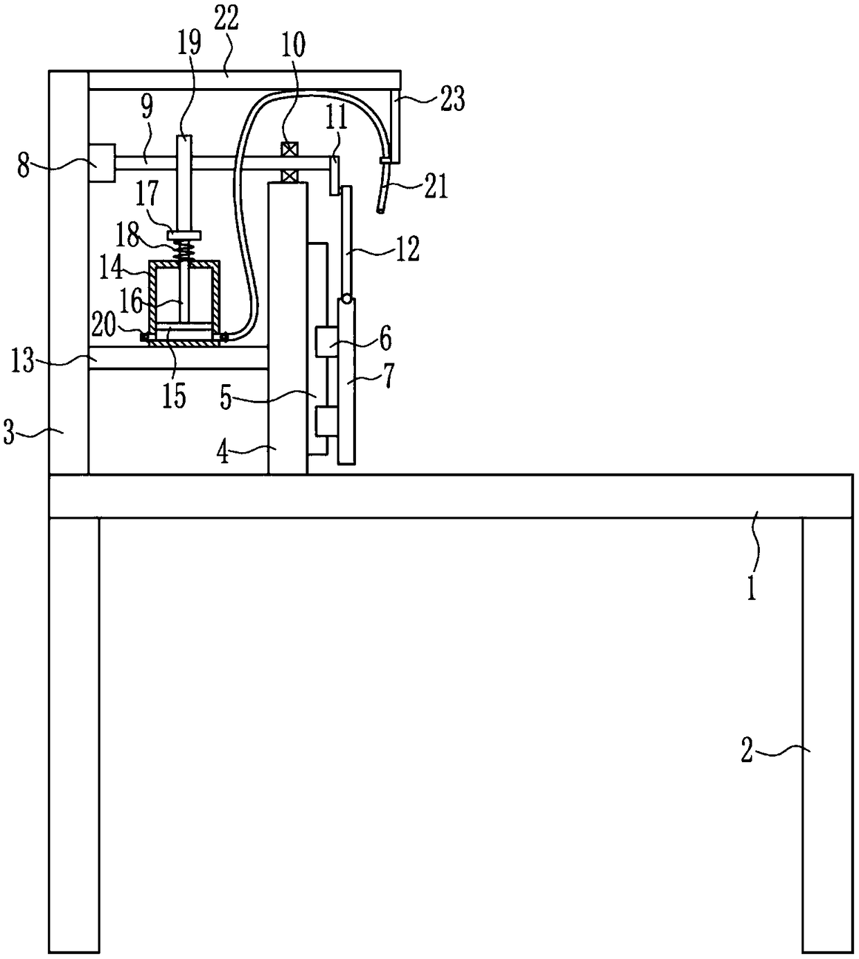
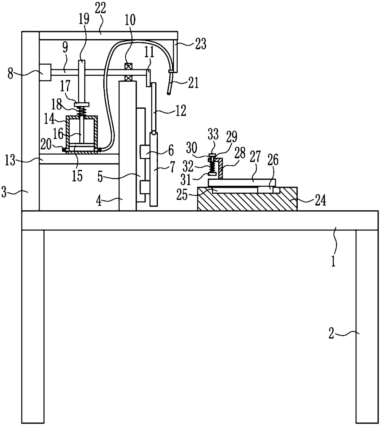
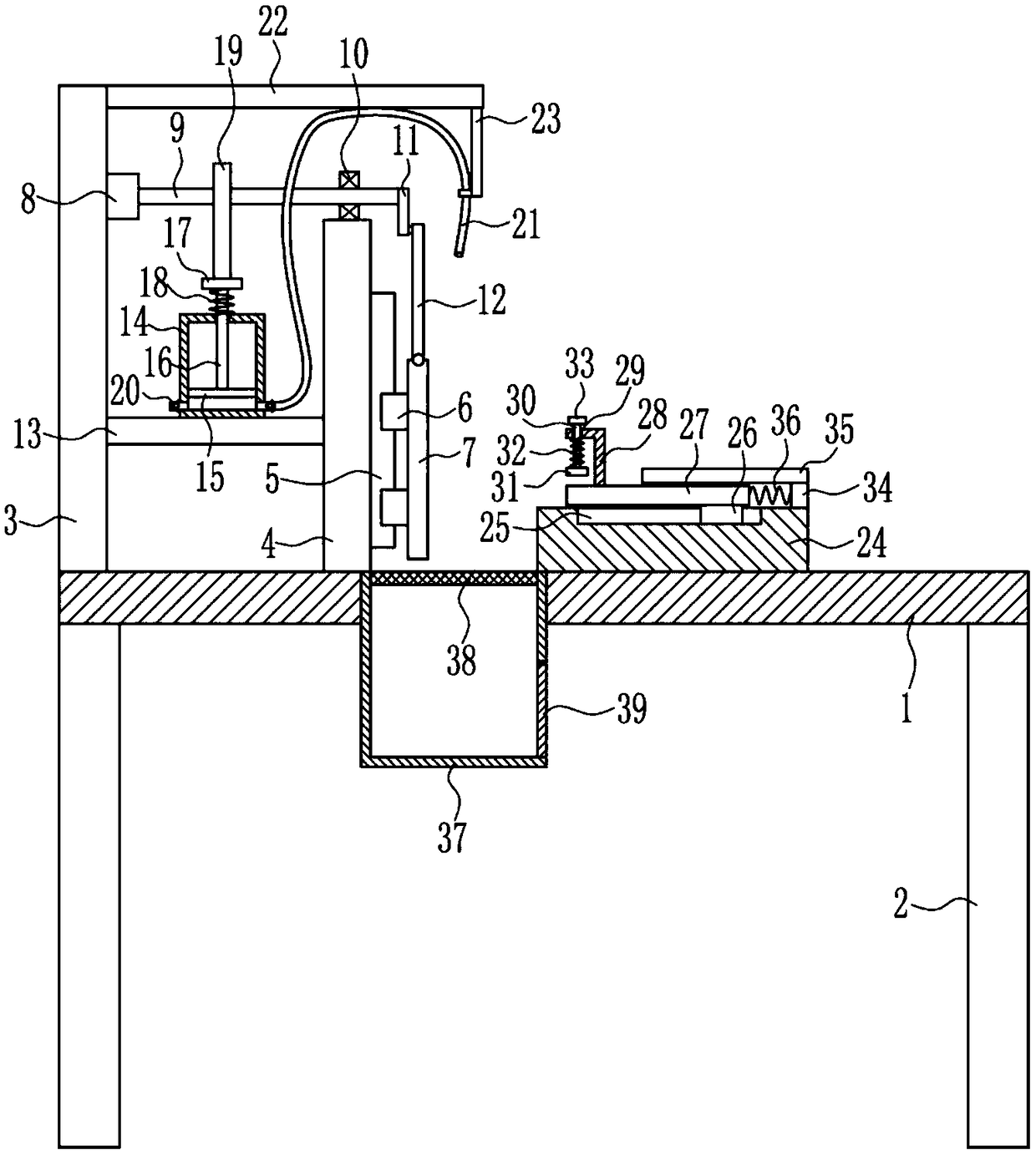
[0021] A device for removing burrs on the surface of mechanical parts, such as Figure 1-3 As shown, it includes a horizontal plate 1, a leg 2, a bracket 3, a vertical plate 4, a slide rail 5, a first slider 6, a file 7, a motor 8, a rotating shaft 9, a bearing seat 10, a rotating rod 11, and a swing rod 12 , mounting plate 13, cylinder block 14, piston 15, push rod 16, contact plate 17, first spring 18, cam 19, one-way valve 20, gas pipe 21, cross bar 22 and vertical bar 23, the bottom left and right sides of the horizontal plate 1 Both sides are connected with outriggers 2, and the left side of the top of the horizontal plate 1 is respectively connected with a support 3 and a vertical plate 4, the support 3 is located on the left side of the vertical plate 4, and the right side of the vertical plate 4 is installed with a slide rail 5, the slide rail 5 is provided with two first sliders 6, the first slider 6 is slidingly matched with the slide rail 5, the right side of the tw...

Embodiment 2

[0023] A device for removing burrs on the surface of mechanical parts, such as Figure 1-3As shown, it includes a horizontal plate 1, a leg 2, a bracket 3, a vertical plate 4, a slide rail 5, a first slider 6, a file 7, a motor 8, a rotating shaft 9, a bearing seat 10, a rotating rod 11, and a swing rod 12 , mounting plate 13, cylinder block 14, piston 15, push rod 16, contact plate 17, first spring 18, cam 19, one-way valve 20, gas pipe 21, cross bar 22 and vertical bar 23, the bottom left and right sides of the horizontal plate 1 Both sides are connected with outriggers 2, and the left side of the top of the horizontal plate 1 is respectively connected with a support 3 and a vertical plate 4, the support 3 is located on the left side of the vertical plate 4, and the right side of the vertical plate 4 is installed with a slide rail 5, the slide rail 5 is provided with two first sliders 6, the first slider 6 is slidingly matched with the slide rail 5, the right side of the two...

Embodiment 3

[0026] A device for removing burrs on the surface of mechanical parts, such as Figure 1-3 As shown, it includes a horizontal plate 1, a leg 2, a bracket 3, a vertical plate 4, a slide rail 5, a first slider 6, a file 7, a motor 8, a rotating shaft 9, a bearing seat 10, a rotating rod 11, and a swing rod 12 , mounting plate 13, cylinder block 14, piston 15, push rod 16, contact plate 17, first spring 18, cam 19, one-way valve 20, gas pipe 21, cross bar 22 and vertical bar 23, the bottom left and right sides of the horizontal plate 1 Both sides are connected with outriggers 2, and the left side of the top of the horizontal plate 1 is respectively connected with a support 3 and a vertical plate 4, the support 3 is located on the left side of the vertical plate 4, and the right side of the vertical plate 4 is installed with a slide rail 5, the slide rail 5 is provided with two first sliders 6, the first slider 6 is slidingly matched with the slide rail 5, the right side of the tw...


PUM


Abstract

The invention relates to equipment for removing burrs, in particular to equipment for removing burrs on the surfaces of mechanical parts. The equipment for removing the burrs on the surfaces of the mechanical parts is high in burr removal efficiency and thorough in removal effect. According to the technical scheme, the equipment for removing the burrs on the surfaces of the mechanical parts comprises a transverse plate, supporting legs, a bracket, a vertical plate, a sliding rail, first sliding blocks, a file, a motor, a rotating shaft, a bearing seat, a rotating rod, a swinging rod, a mounting plate, a cylinder body, a piston and the like. The supporting legs are correspondingly connected to the left and right sides of the bottom of the transverse plate. The bracket and the vertical plateare connected to the left side of the top of the transverse plate. The bracket is positioned on the left side of the vertical plate, and the sliding rail is installed on the right side of the vertical plate. According to the equipment for removing the burrs on the surfaces of the mechanical parts, the burrs on the surfaces of the mechanical parts are removed by the file moving up and down, and the piston moving up and down drives air to be blown out from the end of an air pipe, so that debris generated during burr removal is blown off, the debris is prevented from affecting burr removal efficiency, and the more thorough removal effect is achieved.

Description

technical field [0001] The invention relates to a device for removing burrs, in particular to a device for removing burrs on the surface of mechanical parts. Background technique [0002] Machinery refers to the general term for machines and mechanisms. Machinery is a tool device that can help people reduce the difficulty of work or save labor. Items such as chopsticks, brooms, and tweezers can all be called machines, and they are simple machines. A complex machine is composed of two or more simple machines. These more complex machines are usually called machines. From the point of view of structure and motion, there is no difference between a mechanism and a machine, and it is generally called a machine. [0003] Mechanical parts, also known as mechanical components, are the basic components of machinery, and they are inseparable individual parts that make up machinery and machines. [0004] After the mechanical parts are processed, there will be burrs on the surface. I...

Claims


Application Information

Patent Timeline
Patent Type & Authority Applications(China)
IPC IPC(8): B23D69/00B23D67/00B23Q11/00
CPCB23D69/00B23D67/00B23Q11/00B23Q11/005
Inventor 胡志能蔡小青陈丽
Owner 胡志能
Why Eureka
Try Eureka