
Electric valve and refrigerating cycle system using the electric valve

A technology of electric valves and valve housings, which can be used in fluid circulation arrangements, lifting valves, refrigerators, etc., and can solve problems such as difficult access to valve seats

Active Publication Date: 2020-07-28
SAGINOMIYA SEISAKUSHO INC
View PDF9 Cites 0 Cited by
  • Summary
  • Abstract
  • Description
  • Claims
  • Application Information

AI Technical Summary

Problems solved by technology

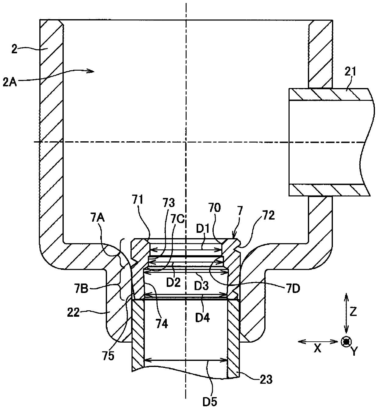
In the electric valve described in Patent Document 1, the solder that has flowed into the inner peripheral surface of the seat ring stays in the groove, making it difficult to reach the valve seat (sealing portion).

Method used


Image

  • Electric valve and refrigerating cycle system using the electric valve
  • Electric valve and refrigerating cycle system using the electric valve
  • Electric valve and refrigerating cycle system using the electric valve

Examples


Embodiment Construction

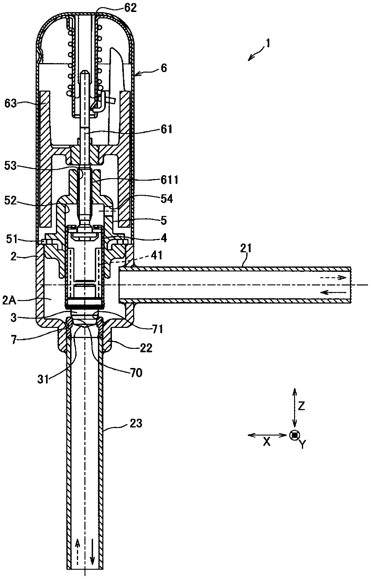
[0025] Hereinafter, each embodiment of the present invention will be described based on the drawings. Such as figure 1 As shown, the electric valve 1 of this embodiment is used in refrigeration cycle systems of air conditioners such as combined air conditioners and indoor air conditioners, and includes a valve casing 2 , a valve core 3 , a valve frame 4 , a support member 5 , and a stepping motor 6 . In this embodiment, the operating direction of the spool 3 is referred to as the Z direction, and two directions approximately perpendicular to the Z direction are referred to as the X direction and the Y direction, respectively.

[0026] The valve casing 2 is formed in a cylindrical shape extending in the Z direction, and accommodates the valve body 3 and the valve frame 4 in the valve chamber 2A inside. Further, a joint pipe 21 communicating with the valve chamber 2A and extending in the X direction is attached to a side surface of the valve housing 2 , and a cylindrical openin...


PUM


Abstract

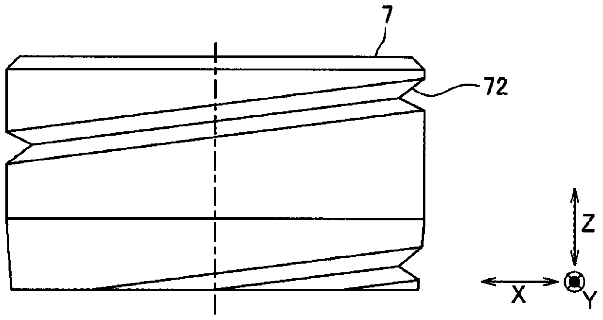
PROBLEM TO BE SOLVED: To provide a motor valve which inhibits a brazing agent from reaching a seal part and enables a valve seat member to be easily press-fitted, and to provide a refrigeration cycle system using the motor valve.SOLUTION: A step part 7C is formed on an inner peripheral surface of a valve seat member 7 to cause a brazing agent to accumulate in the step part 7C and be inhibited from reaching a seal part 71 even if the brazing agent flows into an inner peripheral surface side of the valve seat member 7 when a joint pipe 23 is brazed to a cylindrical opening 22. Further, a thin part 7B is formed closer to a joint pipe 23 side than a thick part 7A in which the seal part 71 is formed to cause the thin part 7B to easily press-fit in the cylindrical opening.SELECTED DRAWING: Figure 2

Description

technical field [0001] The present invention relates to an electric valve and a refrigeration cycle system using the electric valve. Background technique [0002] In general, electric valves are sometimes used as expansion valves in refrigeration cycle systems of air conditioners such as combined air conditioners and room air conditioners. In such an electric valve, the valve seat member is formed separately from the valve case, and the joint pipe is sometimes fixed to the valve case by brazing. At this time, if the molten brazing material flows into the inner peripheral surface side of the valve seat member, reaches the sealing portion (the portion where the valve element is seated or is released from the seat) and solidifies, the port diameter becomes smaller or the valve element is not seated normally, so There may be a decrease in the flow rate and a valve leak. [0003] Therefore, as such an electric valve, an electric valve in which grooves are formed on the inner pe...

Claims


Application Information

Patent Timeline
Patent Type & Authority Patents(China)
IPC IPC(8): F16K1/42F25B41/06
CPCF16K1/42F25B41/31Y02B30/70
Inventor 田边珠实
Owner SAGINOMIYA SEISAKUSHO INC
Learn More