Dynamic speaker with magnet system

A magnetic circuit system and loudspeaker technology, which is applied in the direction of loudspeakers, sensors, and diaphragm damping devices, etc., can solve the problem that the passive damping of the diaphragm is not optimal, and achieve the effect of enhanced suppression

Active Publication Date: 2018-10-09
奥音科技(镇江)有限公司
View PDF7 Cites 2 Cited by
  • Summary
  • Abstract
  • Description
  • Claims
  • Application Information

AI Technical Summary

Problems solved by technology

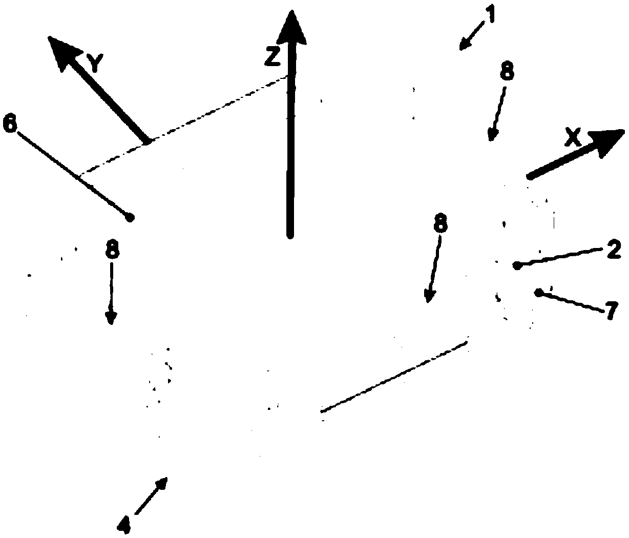
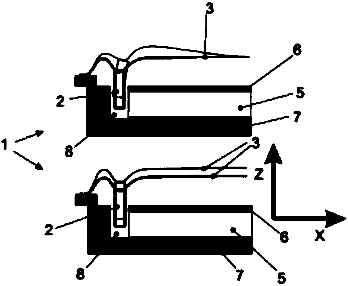
However, engaging a figure-of-eight coil with the front end of a voice coil as disclosed in US 20170026746A1 has proven to be suboptimal for achieving passive damping of the diaphragm

Method used


Image

  • Dynamic speaker with magnet system
  • Dynamic speaker with magnet system
  • Dynamic speaker with magnet system

Examples


Embodiment Construction

[0052] Various implementations are described herein for various apparatuses. Numerous specific details are set forth to provide a thorough understanding of the general structure, function, manufacture and use of the embodiments as described in the specification and illustrated in the drawings. However, it will be apparent to those skilled in the art that the embodiments may be practiced without such specific details. In other instances, well-known operations, components, and components have not been described in detail so as not to obscure the implementations described in the specification. It should be understood by those of ordinary skill in the art that the embodiments described and illustrated herein are non-limiting examples, so it can be appreciated that specific structural and functional details disclosed herein may be representative and do not necessarily limit the scope of the embodiments, which are limited only by be defined by the appended claims.

[0053] Referen...


PUM


Abstract

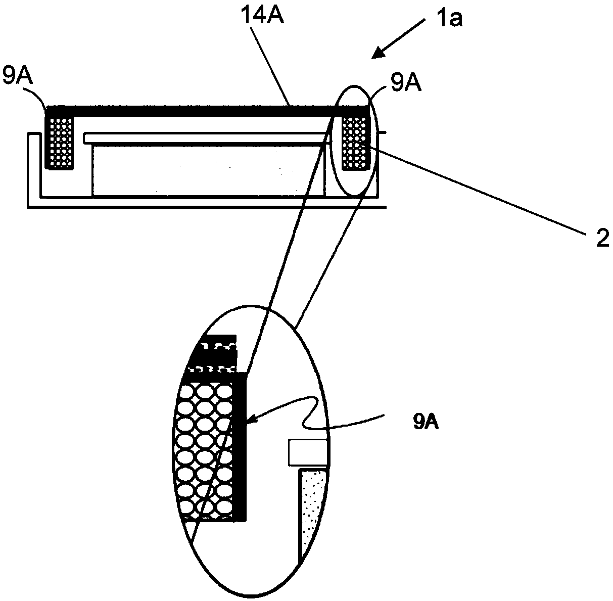
The invention discloses a dynamic speaker with a magnet system. The dynamic loudspeaker driver (1a) comprises a magnet-system; a membrane (3); the membrane being movably mounted with respect to the magnet-system; at least one voice coil (2) attached to the membrane (3) and operatively coupled with the magnet-system; at least one figure 8-shaped coil (9A) attached to the membrane (3) and to a lateral surface of the at least one voice coil (2).

Description

technical field [0001] The present invention relates to a dynamic speaker driver, a speaker comprising the dynamic speaker driver, and a mobile device such as a mobile phone comprising the speaker. [0002] The invention also relates to a method of making a loudspeaker driver. Background technique [0003] Dynamic loudspeaker drivers generally include a magnetic circuit, a diaphragm movably mounted relative to the magnetic circuit, and a voice coil engaged with the diaphragm. The magnetic circuit system includes a magnet, and the voice coil is operatively coupled to the magnet. Generally speaking, a loudspeaker includes an enclosure and at least one dynamic speaker driver mounted in the enclosure. [0004] In operation, an electrical signal is applied to the voice coil, for example via an amplifier. The diaphragm is then moved relative to the magnetic system and relative to the housing under the electrical signal, thereby moving the air. The sound pressure level of a lou...

Claims


Application Information

Patent Timeline
Patent Type & Authority Applications(China)
IPC IPC(8): H04R9/06H04R9/02
CPCH04R9/02H04R9/06H04R2400/11H04R7/26H04R9/025H04R2499/11H04R7/04H04R9/046H04R7/18
Inventor B-D·科勒G·奥特F·瑞宁
Owner 奥音科技(镇江)有限公司
Why Eureka
Try Eureka