Supercharge Your Innovation With Domain-Expert AI Agents!

Centrifugal pump back plate disassembling and assembling device and method

A back plate and centrifugal pump technology, applied in workpiece clamping devices, manufacturing tools, etc., can solve the problems of high labor cost, low safety, time-consuming and labor-intensive, etc., to reduce labor costs, improve safety, and prevent tilting. Effect

Active Publication Date: 2018-10-12
CHINA SHENHUA ENERGY CO LTD +1
View PDF7 Cites 0 Cited by
  • Summary
  • Abstract
  • Description
  • Claims
  • Application Information

AI Technical Summary

Problems solved by technology

In the process of realizing the invention, the inventor found that the above-mentioned backboard has the following deficiencies in the disassembly process: first, after the backboard is disassembled, it needs to be hung to the work area through a hook, and the hook is directly hooked on the backboard , the weight of the backboard is relatively large and the surface is relatively smooth. During the hanging process, the backboard is easy to fall and injure the workers, and the safety is low; It is time-consuming, labor-intensive, labor-intensive and labor-intensive for the operator to lift the backboard to prevent the backboard from toppling over.

Method used


Image

  • Centrifugal pump back plate disassembling and assembling device and method
  • Centrifugal pump back plate disassembling and assembling device and method
  • Centrifugal pump back plate disassembling and assembling device and method

Examples


Embodiment Construction

[0022] The directional terms such as up, down, left, right, front, back, front, back, top, and bottom that are mentioned or may be mentioned in this specification are defined relative to the structures shown in the drawings. The words " "Inside" and "outside" respectively refer to the direction toward or away from the geometric center of a specific component. They are relative concepts, so they may change accordingly according to their different positions and different usage states. Accordingly, these or other directional terms should not be construed as limiting terms.

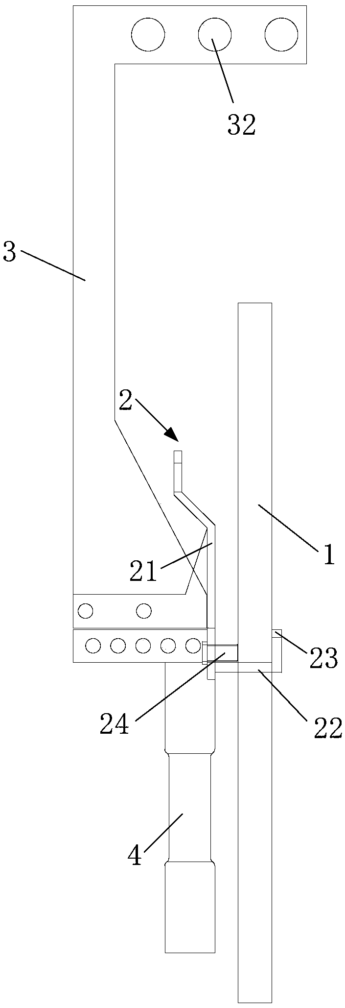
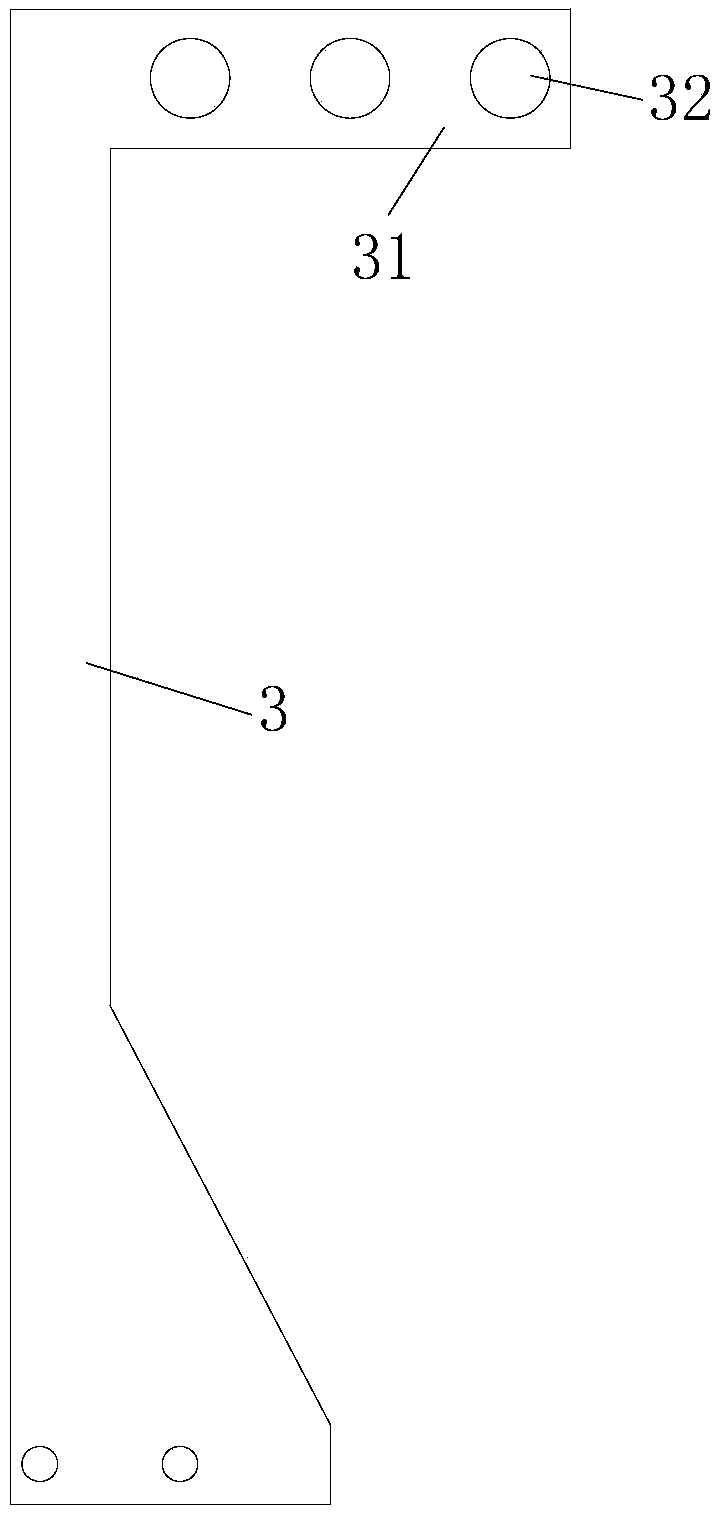
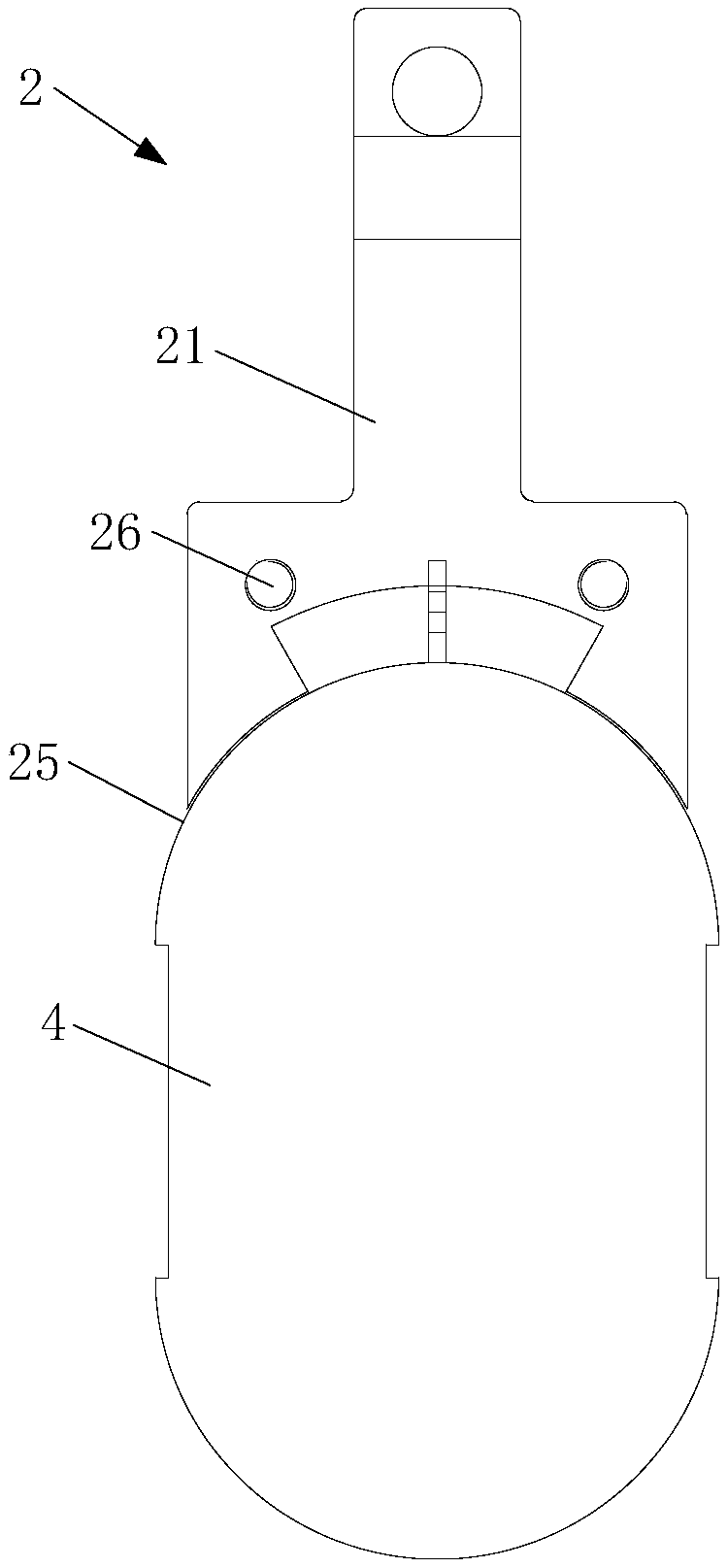
[0023] figure 1 Schematic diagram of the structure of the installation and removal device for the back plate of the centrifugal pump provided by the optional embodiment of the present invention, figure 2 The structural diagram of the bracket provided for the optional embodiment of the present invention, such as Figure 1 to Figure 2 As shown, the present invention provides a centrifugal pump back panel dis...


PUM


Abstract

The invention discloses a centrifugal pump back plate disassembling and assembling device and method. The centrifugal pump back plate disassembling and assembling device comprises a back plate which is provided with a connection hole, and further comprises a supporting frame and a bracket, wherein the supporting frame comprises a backup plate, a supporting plate and a limiting plate which are connected in sequence, the backup plate and the limiting plate are oppositely arranged, the backup plate is located on one side of the back plate, the limiting plate penetrates through the connection holeto be arranged on the other side of the back plate, and the supporting plate is arranged in the connection hole; and the first end of the bracket is connected with the backup plate, the second end ofthe bracket extends in the direction away from the center axis of the connection hole, and hanging holes are formed in the second end of the bracket. The centrifugal pump back plate disassembling andassembling method is used for disassembling and assembling the back plate. According to the centrifugal pump back plate disassembling and assembling device and method, the disassembling and assembling safety of the centrifugal pump back plate is improved, the time required for disassembling and assembling the centrifugal pump back plate is saved, the labor intensity is relieved, and the manpowercost is reduced.

Description

technical field [0001] The invention relates to the technical field of mechanical equipment, in particular to a device and method for disassembling and disassembling the back plate of a centrifugal pump. Background technique [0002] Centrifugal pumps, as a general-purpose machine, play an important role in the national economy and are widely used in industries such as electric power, metallurgy, coal, and building materials to transport various liquids or slurries containing solid particles. The back plate of the centrifugal pump is a wearable part, and the replacement cycle is 1-2 years. [0003] In the prior art, there is no special removal tool for the back plate of the centrifugal pump. When the back plate needs to be disassembled and replaced, it generally requires a number of workers to cooperate to disassemble the back plate from the centrifugal pump and replace the new back plate. Installed on a centrifugal pump. In the process of realizing the invention, the inve...

Claims


Application Information

Patent Timeline
Patent Type & Authority Applications(China)
IPC IPC(8): B25B11/02
CPCB25B11/02
Inventor 姬文伟焦钊白刘贵侯金龙王金平张丙祥
Owner CHINA SHENHUA ENERGY CO LTD
Features
  • R&D
  • Intellectual Property
  • Life Sciences
  • Materials
  • Tech Scout
  • Unparalleled Data Quality
  • Higher Quality Content
  • 60% Fewer Hallucinations
Learn More