
Movable type gripping robot

A robot and mobile technology, applied in manipulators, program-controlled manipulators, manufacturing tools, etc., can solve the problems of difficult operation, inaccurate grasping range, low efficiency, etc. Take a wide range of effects

Pending Publication Date: 2018-10-12
振东科技秦皇岛有限公司
View PDF8 Cites 2 Cited by
  • Summary
  • Abstract
  • Description
  • Claims
  • Application Information

AI Technical Summary

Problems solved by technology

[0002] In the process of industrial production and emergency rescue, there are many dangerous tasks, such as oil pressure, friction press bottoming, forging, and rescue in complex geographical environments. If it is done manually, it is not only difficult to operate, but also often causes work-related accidents, and Some of the work has a relatively large workload. If it is completed by an individual, it will require greater labor intensity and low efficiency. With the development of robot technology, robots or manipulators are generally used for some dangerous and labor-intensive tasks. Complete, the conventional grasping robot is fixed and non-movable. For example, the application number 201520845511.3 published a "Grassing Device for an Intelligent Robot", which mainly includes a base, a lifting cylinder, a telescopic cylinder, a grasping arm and a grasping The entire mechanism is installed on the base, the mechanism cannot be moved, and the range that can be grasped is small. The overall performance of the linkage mechanism using the pneumatic device is unstable, and the grasping range is not accurate. Therefore, a new type of mobile grasping robot is needed.

Method used


Image

  • Movable type gripping robot
  • Movable type gripping robot
  • Movable type gripping robot

Examples


Embodiment Construction

[0014] The technical solutions of the present invention will be further specifically described below through the embodiments and in conjunction with the accompanying drawings.

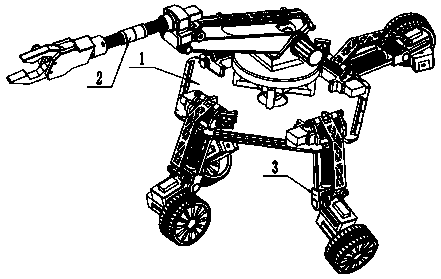
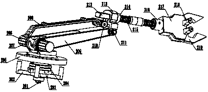
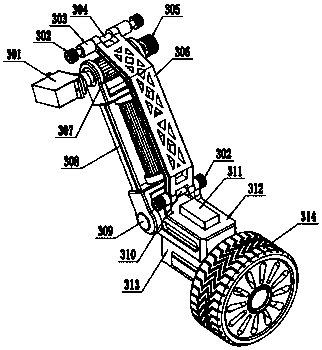
[0015] Example figure 1 , figure 2 , image 3 , Figure 4 As shown, a mobile grabbing robot includes: a main installation chassis 1, a grabbing unit 2, and a walking unit 3. It is characterized in that: the main installation chassis 1 is rhombus-shaped and has a circular hole in the middle, and the grabbing unit 2 through the circular hole and connected with the main installation chassis 1; there are protruding mounting seats near the four vertices of the rhombus chassis, and the traveling unit 3 is installed on the protruding mounting seat of the main mounting chassis 1, and the four traveling units 3 axis The adjacent angle is 90°.

[0016] The further described mobile grabbing robot is characterized in that: the grabbing unit 2 includes: a turntable reducer 201, a turntable motor base 202, a la...


PUM


Abstract

The invention provides a movable type gripping robot. The movable type gripping robot comprises a main mounting bottom disc, a gripping unit and walking units. The movable type gripping robot is characterized in that the main mounting bottom disc is in a rhombus shape, and a round hole is formed in the middle of the main mounting bottom disc; the gripping unit penetrates the round hole and is connected with the main mounting bottom disc; protruding mounting seats are arranged adjacent to four vertexes of the rhombus bottom disc; the walking units are mounted on the protruding mounting seats ofthe bottom disc; and the included angels of adjacent axes of the four walking units are 90 degrees. According to the movable type gripping robot, four speed reducers are mounted at joints of a mechanical arm, so that the multi-freedom-degree motion is achieved; the gripping range is large; servo motors are adopted as motors of the speed reducers, so that gripping is conducted more precisely; thefour walking units are uniformly distributed in the circumferential direction, and the leg swing motion can be achieved; rotation angels of feet can be controlled; the obstacle crossing ability is excellent; and motion performance of the movable type gripping robot is enhanced.

Description

technical field [0001] The invention relates to the technical field of object moving and handling in the process of production rescue and the like, in particular to a mobile grabbing robot. Background technique [0002] In the process of industrial production and emergency rescue, there are many dangerous tasks, such as oil pressure, friction press bottoming, forging, and rescue in complex geographical environments. If it is done manually, it is not only difficult to operate, but also often causes work-related accidents, and Some of the work has a relatively large workload. If it is completed by an individual, it will require greater labor intensity and low efficiency. With the development of robot technology, robots or manipulators are generally used for some dangerous and labor-intensive tasks. Complete, the conventional grasping robot is fixed and non-movable. For example, the application number 201520845511.3 published a "Grassing Device for an Intelligent Robot", which ...

Claims


Application Information

Patent Timeline
Patent Type & Authority Applications(China)
IPC IPC(8): B25J5/00B25J9/10B25J9/02
CPCB25J5/007B25J9/02B25J9/10
Inventor 徐金路
Owner 振东科技秦皇岛有限公司
Learn More