Pressure plate structure for clutch
A technology of clutch and pressure plate, applied in the field of clutch, can solve the problems of failure of separation system, complicated structure of pressure plate, hidden safety hazards, etc., so as to avoid separation failure, reduce the risk of wear of pressure plate, and reduce the effect of motion friction
- Summary
- Abstract
- Description
- Claims
- Application Information
AI Technical Summary
Problems solved by technology
Method used
Image
Examples
Embodiment Construction
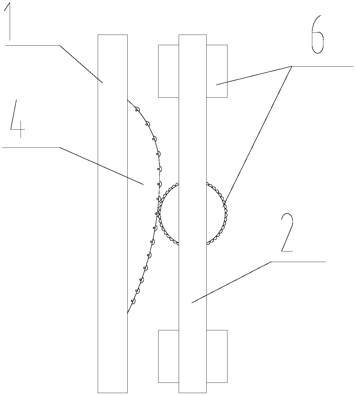
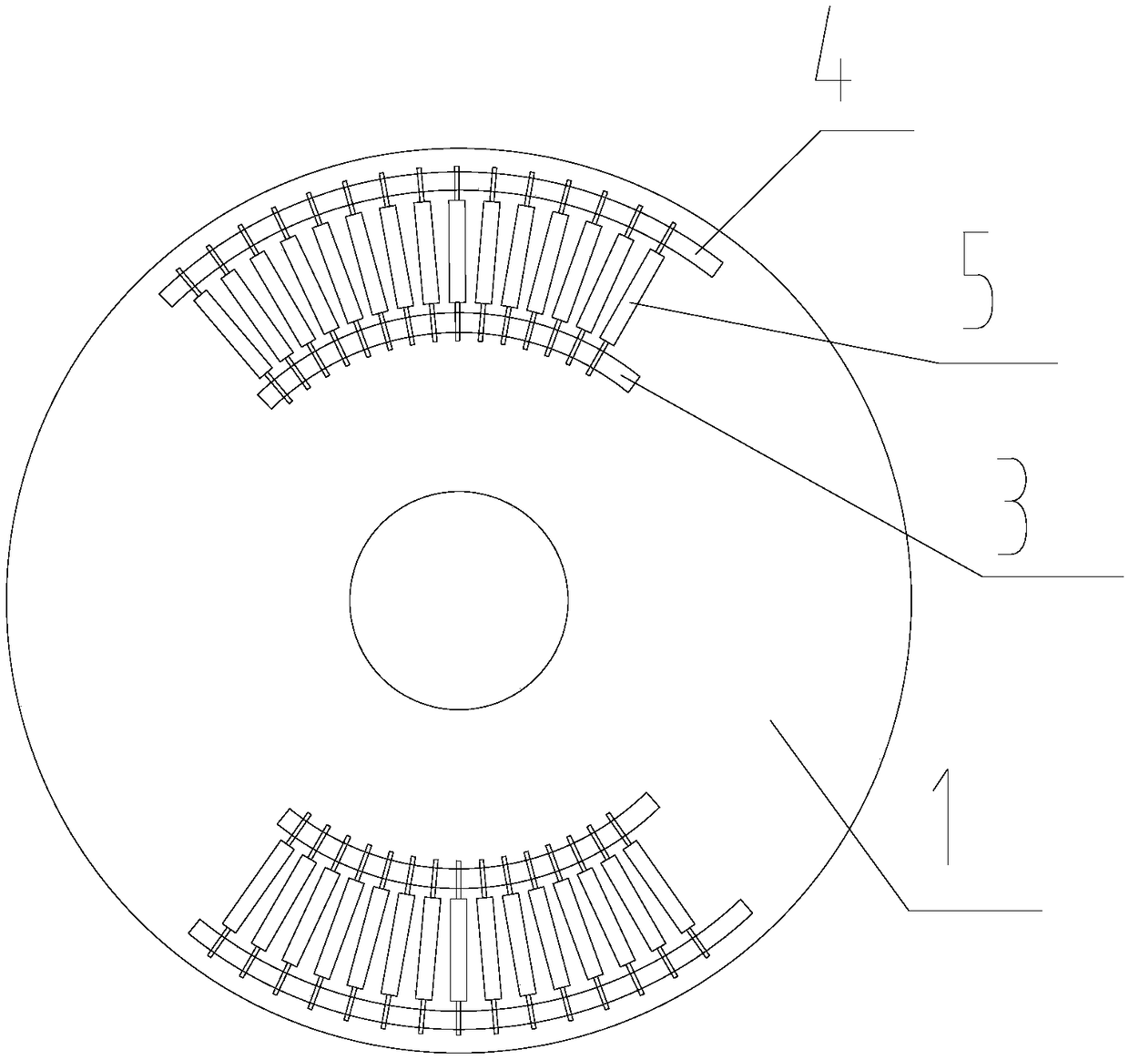
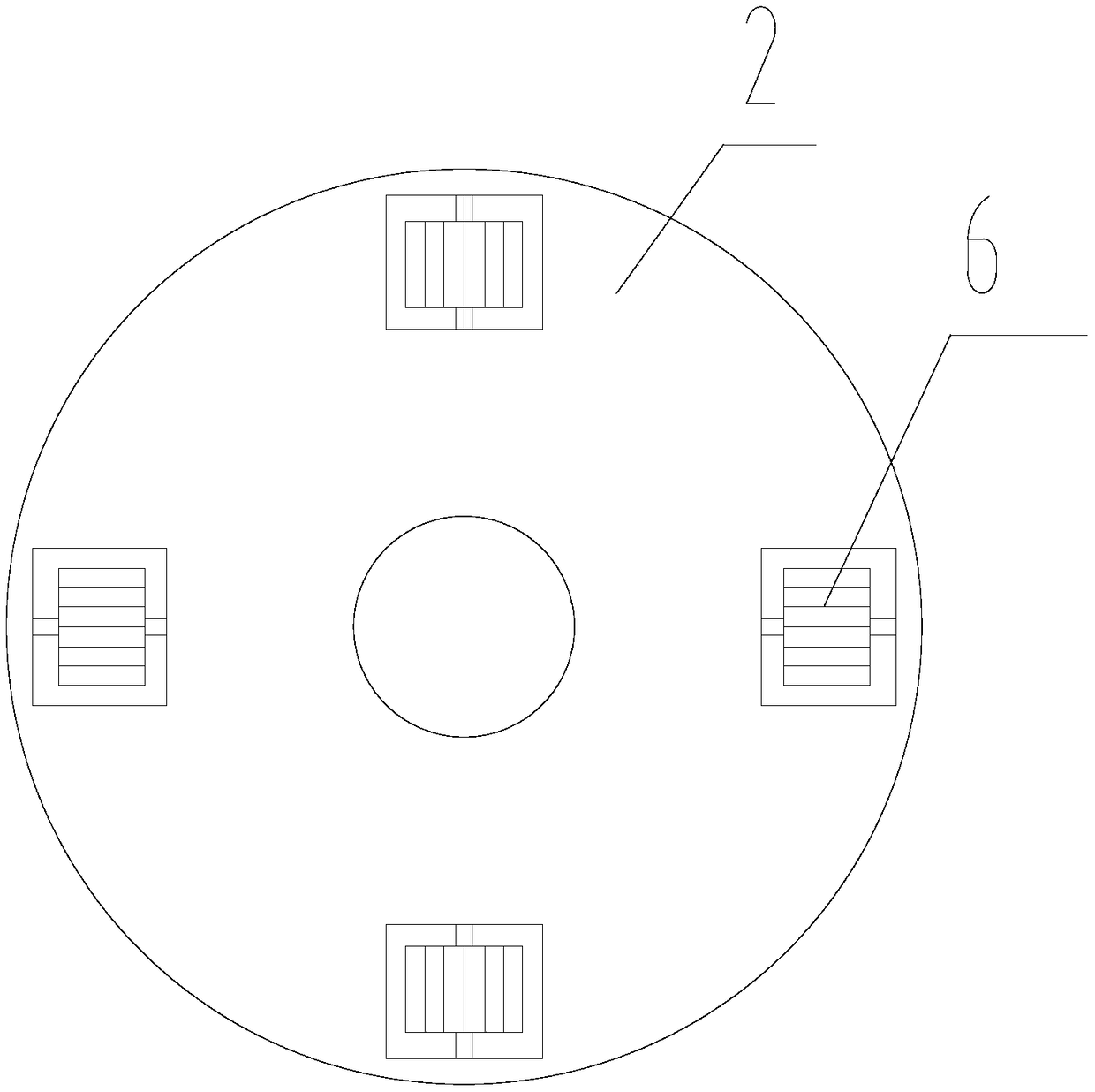
[0018] refer to figure 1 , a pressure plate structure for a clutch proposed by the present invention includes: a driven plate 1 and a driving plate 2, the driven plate 1 and the driving plate 2 are both sleeved on the input shaft of the clutch, and the driven plate 1 and the input The shafts are optically connected, and the driven disc 1 moves linearly, that is, the driven disc 1 is isolated from the motion of the input shaft and slides along the axis of the input shaft. Specifically, in this embodiment, the driven disc 1 is mounted on the input shaft through bearings for motion isolation. During specific implementation, a guide rod parallel to the direction of the input shaft can also be provided, so that the guide rod passes through the driven disk 1 and is slidably connected with the driven disk 1, so that the linear movement of the driven disk 1 is limited by the guide rod.
[0019] The driving disc 2 is relatively stationary relative to the input shaft in the axial direc...
PUM
 Abstract
Description
Claims
Application Information
 - R&D
- Intellectual Property
- Life Sciences
- Materials
- Tech Scout
- Unparalleled Data Quality
- Higher Quality Content
- 60% Fewer Hallucinations
Browse by: Latest US Patents, China's latest patents, Technical Efficacy Thesaurus, Application Domain, Technology Topic, Popular Technical Reports.
© 2025 PatSnap. All rights reserved.Legal|Privacy policy|Modern Slavery Act Transparency Statement|Sitemap|About US| Contact US: help@patsnap.com


