Laser-based large-area glass plate local convex-concave defect detection method

A defect detection and glass plate technology, used in optical testing flaws/defects, measuring devices, scattering characteristics measurement, etc., can solve problems such as unaffordable, expensive, and narrow detection widths of enterprises, and solve the problem of yield and manpower. High cost and the effect of solving recruitment difficulties

Inactive Publication Date: 2018-10-12
长春新产业光电技术有限公司
View PDF7 Cites 7 Cited by
  • Summary
  • Abstract
  • Description
  • Claims
  • Application Information

AI Technical Summary

Problems solved by technology

This method has the following disadvantages: the detection speed is slow, which cannot meet the production efficiency; the detection range is narrow, and multiple sets of parallel work are required, and the price is very expensive, which cannot be afforded by enterprises.
[0004] Therefore, the detection of convex and concave defects in large format glass plates is facing a very serious challenge, and a method is needed to solve this problem

Method used


Image

  • Laser-based large-area glass plate local convex-concave defect detection method
  • Laser-based large-area glass plate local convex-concave defect detection method
  • Laser-based large-area glass plate local convex-concave defect detection method

Examples


Embodiment 1

[0038] Example 1 Convex defect detection:

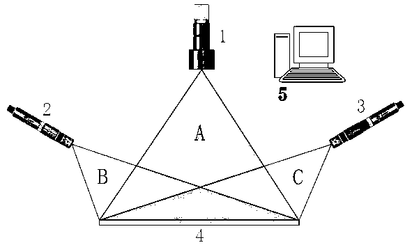
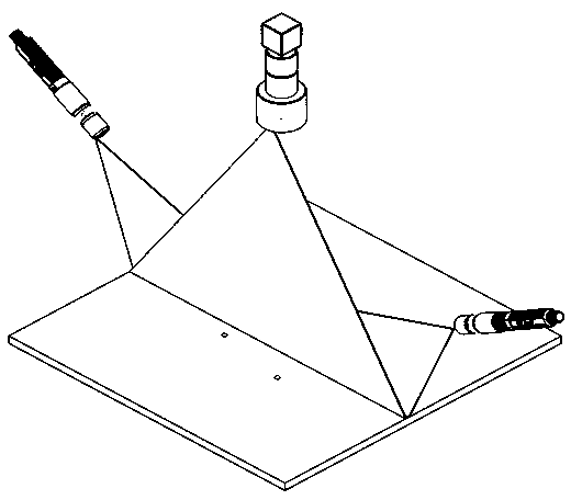
[0039] The 405nm low-angle laser on the left is irradiated on the local convex defect, and there will be a large reflection of light on the side of the convex position facing the left 405nm laser, and a bright blue light spot will appear in the imaging of the color line scan camera. There are no large reflections on the side facing away from the left 405nm laser.

[0040] At the same time, when the right low-angle 655nm laser is irradiated on the same local convex defect, a large amount of light will be reflected on the side of the convex position facing the right 655nm laser, and a bright red light spot will appear in the imaging of the color line scan camera. No large reflections occur on the side facing away from the laser on the right.

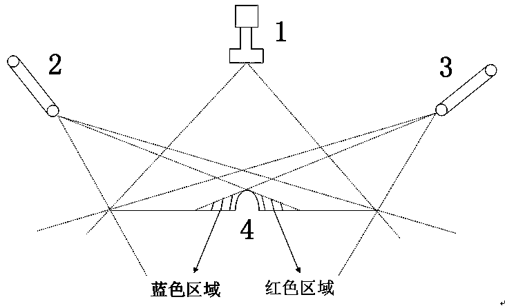
[0041] In the imaging of the color line scan camera, the two lasers emit light at the same time, so a pair of light spots appear on the local convex defect image, the left side is blue, and the ...

Embodiment 2

[0043] Embodiment 2 local concave defect detection:

[0044] The 405nm low-angle laser on the left is irradiated on the local convex defect, and there will be a large reflection of light on the side of the convex position facing the left 405nm laser, and a bright blue light spot will appear in the imaging of the color line scan camera. There are no large reflections on the side facing away from the left 405nm laser.

[0045] When the low-angle 655nm laser on the right is irradiated on the same local convex defect, a large amount of light will be reflected on the side of the convex position facing the right 655nm laser, and a bright red light spot will appear in the imaging of the color line scan camera. No large reflections occur on the side facing away from the laser on the right.

[0046] In the imaging of the color line scan camera, the two lasers emit light at the same time, so a pair of light spots appear on the local convex defect image, the left side is blue, and the r...


PUM


Abstract

The invention relates to a laser-based large-area glass plate local convex-concave defect detection method. The method is characterized in that a laser line generating unit shapes laser lights emittedby two line lasers from a point shape into a line shape, the network port of a color line array industrial camera is connected with the network port of an industrial computer through a network cable,the two line laser device sources are respectively placed on the left side and the right side of a glass plate transmission line, and are located at the same plane height, an included angle between every laser device and a glass plate is 20 DEG, and the laser lines of the two laser devices are superposed on the glass plate; and the color line array industrial camera is arranged perpendicular to the glass plate and is located at the middle position of the glass plate transmission line, and the color line array camera collects images and performs operations when passing through the glass platetransmission line. The method solves the problem of accurate positioning of the type of a defect and timely feedback of the type to a former corresponding process in the glass production process, andalso solves the yield problem of large-area glass.

Description

technical field [0001] The invention relates to a method for detecting local convex and concave defects of a large-format glass plate, and relates to a method for detecting defects of a high-reflective flat plate. Background technique [0002] At present, in the production process of large-format glass plates, due to factors such as the previous production process, there will be local convex and concave defects on the surface. Convex defects include defects such as drops, and concave defects include defects such as holes. These defects have a great impact on the quality of the product, so online real-time detection must be carried out during the production process. Since the causes of convex defects and concave defects belong to different processes at the front end of manufacturing, once a problem is found, it will be reported to the police immediately and the corresponding production process of the previous sequence will be quickly adjusted to avoid batch defect waste. ...

Claims


Application Information

Patent Timeline
Patent Type & Authority Applications(China)
IPC IPC(8): G01N21/88G01N21/95G01N21/55
CPCG01N21/55G01N21/8806G01N21/8851G01N21/95G01N2021/8861G01N2021/8887
Inventor 刘立峰王婧媛刘晓宏宋岩刘衡郑权邓岩张艳波
Owner 长春新产业光电技术有限公司
Why Eureka
Try Eureka