Eureka AIR delivers breakthrough ideas for toughest innovation challenges, trusted by R&D personnel around the world.

A wavefront-aware adaptive optics imaging system and imaging method thereof

An imaging method and imaging system technology, applied in optics, optical components, instruments, etc., can solve the problems of huge data processing requirements, functional coupling, high system cost, etc., and achieve high-speed wavefront correction, speed improvement and wavefront distortion correction effect of ability

Active Publication Date: 2020-12-18
YIBIN UNIV
View PDF6 Cites 0 Cited by
  • Summary
  • Abstract
  • Description
  • Claims
  • Application Information

AI Technical Summary

Problems solved by technology

[0017] The disadvantage of the above-mentioned prior art is that it mainly faces the coupling of adaptive optics far-field detection and target imaging functions, that is, both target imaging and far-field detection are realized by system far-field and target cameras
[0018] The working mode of the camera is difficult to meet the requirements of large field of view, large target surface detection and adaptive optics high frame rate far-field detection for target imaging at the same time. more expensive
Even in applications regardless of cost, the large-scale images detected by the large target surface of the imaging camera will result in huge data processing requirements, which will pose great challenges to the data processing capabilities of the wavefront controller and the system data transmission bandwidth.

Method used


Image

  • A wavefront-aware adaptive optics imaging system and imaging method thereof
  • A wavefront-aware adaptive optics imaging system and imaging method thereof
  • A wavefront-aware adaptive optics imaging system and imaging method thereof

Examples


Embodiment 1

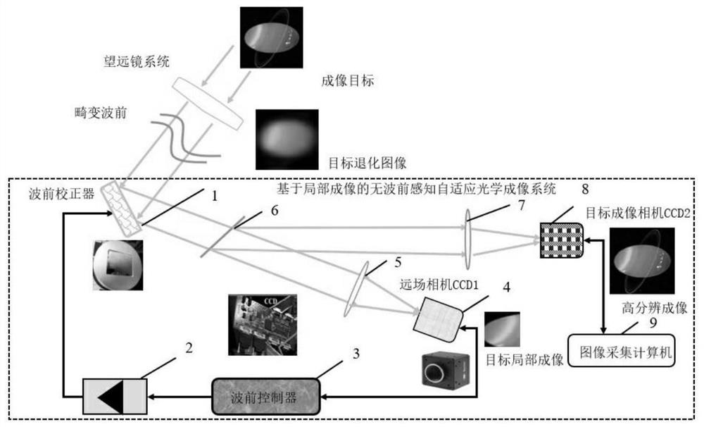
[0058] Such as figure 1 As shown, the imaging system mainly consists of a wavefront correction unit deformable mirror 1, a high-voltage amplifier 2, a wavefront controller 3, a far-field detection camera 4, and a focusing lens A5, a beam splitter 6, a focusing lens B7, and a target imaging camera 8 , Image acquisition computer 9 components.

[0059] The wavefront correction unit deformable mirror 1 is used for generating a conjugate surface shape of wavefront distortion according to the driving voltage output by the high-voltage amplifier 2, so as to correct wavefront aberrations.

[0060] The high-voltage amplifier 2 is used to: amplify the multi-channel control small signal output by the wavefront controller 3 to drive the deformable mirror 1 of the wavefront correction unit.

[0061] The wavefront controller 3 is used to: receive the image signal from the far-field detection camera 4 , and output multi-channel control small signals to the high-voltage amplifier 2 by using ...

Embodiment 2

[0082] This embodiment only describes the differences of Embodiment 1, and the similarities will not be described again.

[0083] The imaging method based on the non-wavefront-aware adaptive optics imaging system can be replaced by the optimization algorithm based on the aberration mode to complete the correction of the wavefront aberration and the restoration of the high-resolution target image. Specific steps are as follows:

[0084] Step 1: The controller generates the independent and identically distributed aberration mode coefficient random quantity Δα at time K (k) =(Δα 3 ,Δα 4 …Δα M ), because the deformable mirror does not correct translational, tilt aberrations in the X and Y directions, so the aberration image starts from the third order, and the total number of preset aberration items is M-3. Using the relationship matrix C of the mode coefficient and the influence function of the deformable mirror zv , the coefficient random quantity Δα (k) Multi-channel cont...


PUM


Abstract

The invention discloses a wavefront-free perception adaptive optical imaging system and an imaging method thereof. The wavefront-free perception adaptive optical imaging system includes a wavefront controller, a far field detection camera, a high voltage amplifier, a wavefront correction unit deformation reflector, an acquisition computer and a target imaging camera, wherein the wavefront controller adopts an optimization searching control algorithm according to the target local imaging received by the far field detection camera, outputs multi-channel voltage control signals to the high voltage amplifier and then drives the wavefront correction unit deformation reflector to realize correction of wavefront to enable the image acquisition computer to receive high resolution target images ofthe target imaging camera. The wavefront-free perception adaptive optical imaging system and the imaging method thereof have the advantages of improving the adaptive optical correction speed and the wavefront distortion correction capability, and obtaining target images with high resolution.

Description

technical field [0001] The invention relates to the technical field of optical imaging, in particular to a wavefront-aware adaptive optical imaging system and an imaging method thereof. Background technique [0002] Wavefront-free adaptive optics is widely used in wavefront phase jumps, difficult to obtain beacons, faint targets and some special applications, such as: confocal microscopes, space targets, remote sensing, optical coherence tomography and other imaging applications; to achieve imaging Feedback correction of system optical errors and slowly varying wavefront aberrations, and high-resolution images are obtained. The speed of wavefront correction in non-wavefront-aware adaptive optics systems mainly depends on the wavefront correction algorithm and the frame rate of the far-field detection camera. When the system adopts a certain control correction algorithm, the wavefront correction iteration speed mainly depends on the far-field camera detection frame rate, tha...

Claims


Application Information

Patent Timeline
Patent Type & Authority Patents(China)
IPC IPC(8): G02B27/00
CPCG02B27/0025
Inventor 文良华程翔程晓洪邵菊香
Owner YIBIN UNIV
Why Eureka
Eureka Blog
Learn More